

CNC Aerospace Parts Solution
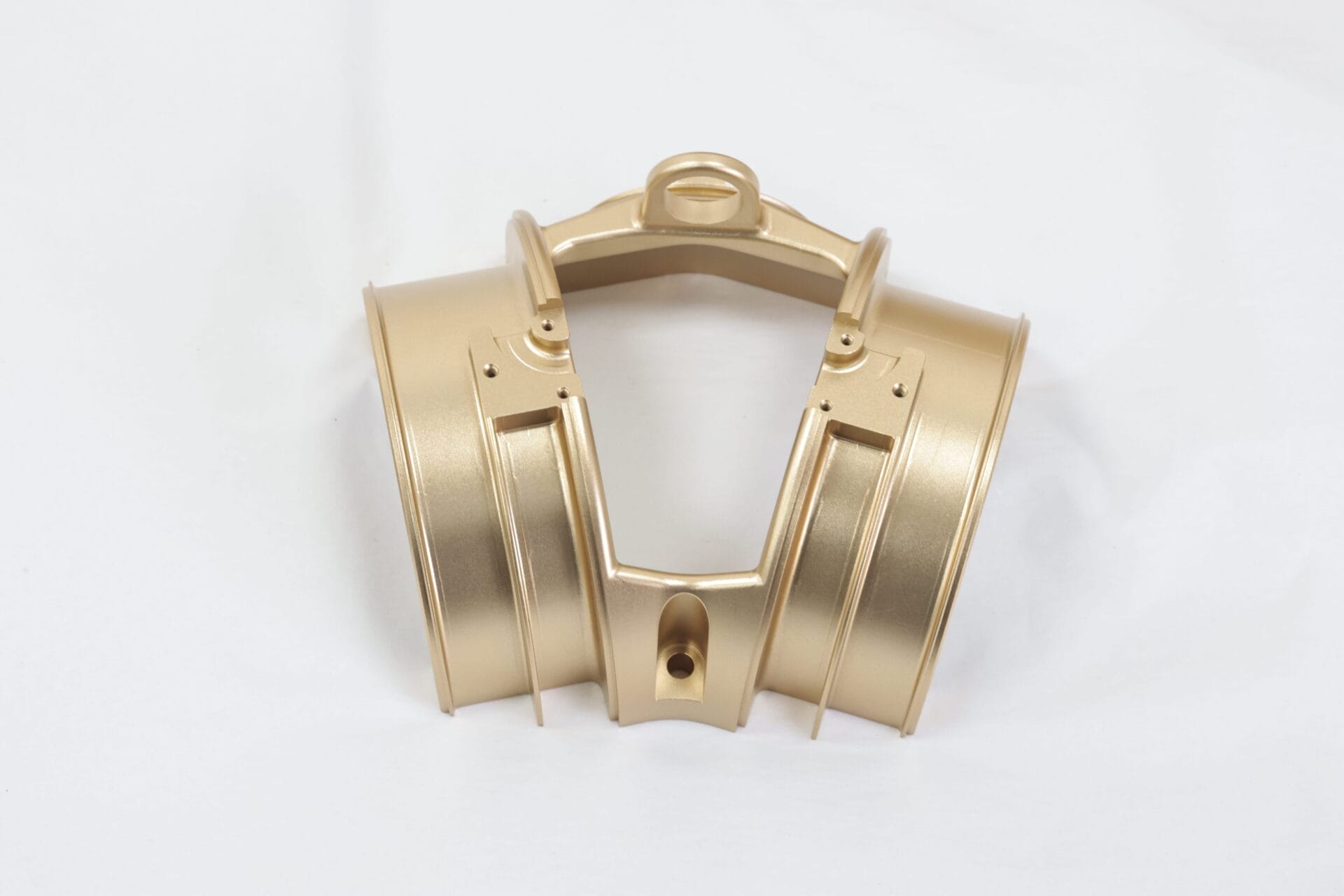
This product is used in the main slurry clamp for aviation. It is made of A7075-T6 and its surface treatment is hard anodized. It is supplied to Dassault Aircraft Manufacturing Company of France. In the Beginning, Dassault does not trust us can accomplish aircraft aviation accessories, our sales with Dassault Aircraft Manufacturing Company’s procurement and Technology Dept in-depth communication, for example, our successful cooperation case, such as our cooperation experience with China Southern Airlines, such as a case with Boeing’s subsidiaries, and invited Dassault Aircraft Manufacturing Company to visit our factory in Shenzhen, China. Dassault Aircraft Manufacturing Company is impressed by our professionalism and sincerity and is willing to Place a trial Order When the Trial Order impressed them. this main pulp folder is our first product in cooperation with Dassault Aircraft Manufacturing Company.

The outer diameter of this product is 35mm and the length is 94mm. The difficulty in processing lies in the first use of turning and milling. and then CNC machining. Long time-consuming, high precision requirements, high accuracy for secondary clamping.
As shown in the above drawings, the difficulty of processing this main pulp clamp is only that the depth of the middle hole is 7-0, +0.015. If it is processed according to the traditional drilling method, the depth tolerance of the middle hole cannot be guaranteed, after Yijin Solution technical department and the engineering department jointly studied and Repeat tried and tested, and finally completed the mesoporous by means of copper discharge after the completion of the processing. The research of this technology and the speed and professionalism of solving the problem won the height of the French Dassault Aircraft Manufacturing Company. Evaluate and place orders to let us produce and lay a solid foundation for continued ongoing cooperation!

Detailed Interpretation of Machining Accuracy
Machining accuracy is the degree of conformity between the three geometric parameters of the actual surface size, shape, and position of the part after machining and the ideal geometric parameters required by the drawing. The ideal geometric parameter is the average size in terms of size; in the case of surface geometry, it is an absolute circle, cylinder, plane, cone, and straight line; in terms of the mutual position of the surfaces, it is absolutely parallel, Vertical, coaxial, symmetrical, etc. The deviation between the actual geometric parameters of the part and the ideal geometric parameters is called a machining error.
Yijin Solution has more than 20 years of machining experience in technical operators to control processing accuracy. The use of 3D design services is key to our process, as it allows us to create detailed digital models and simulations before the machining process begins. This ensures that all parts are manufactured to exact specifications, minimizing errors and improving the overall efficiency of production.
A Brief Introduction to Processing Accuracy
Machining accuracy is mainly used to produce products. Machining accuracy and machining errors are terms used to evaluate the geometric parameters of the machining surface. Machining accuracy is measured by tolerance grades. The smaller the grade value, the higher the precision; the machining error is expressed by a numerical value. The larger the value, the larger the error. High processing accuracy means small processing errors.
There are 20 tolerance levels from IT01, IT0, IT1, IT2, IT3 to IT18. Among them, IT01 indicates that the part has the highest machining accuracy, and IT18 indicates that the part has the lowest machining accuracy. Generally, IT7 and IT8 have medium machining accuracy levels. The actual parameters obtained by any machining method will not be absolutely accurate.
From the perspective of the function of the part, as long as the machining error is within the tolerance range required by the part drawing, it is considered that the machining accuracy is guaranteed. Machining accuracy is inseparable from skilled technical operators and excellent advanced equipment. Yijin Solution not only has skilled technical operators, but also uses advanced precisions such as 3 axes, 4 axes, 5 axes, and CNC lathes from Germany and Switzerland. Equipment to ensure accuracy.
The Difference Between Accuracy and Precision
-
Accuracy
Refers to the closeness degree between the obtained measurement result and the true value. The high accuracy of the measurement means that the system error is small. At this time, the average value of the measurement data deviates from the true value, but the data is scattered, that is, the size of the accidental error is not clear.
-
Precision
Refers to the Reproducibility and consistency between the results obtained from repeated measurements using the same reserve sample. It is possible that the precision is high, but the accuracy is not accurate. For example, the three results obtained by using a length of 1 mm are 1.051 mm, 1.053, and 1.052 respectively. Although their precision is high, they are not accurate. Accuracy indicates the accuracy of the measurement results, and precision indicates the repeatability and reproducibility of the measurement results. Precision is a prerequisite for accuracy. Yijin Solution also has advanced measuring equipment and testing equipment, three-dimensional testing equipment, two-dimensional testing equipment, etc.
-
Dimensional Accuracy
Refers to the degree of conformity between the actual size of the part after machining and the center of the tolerance zone of the part size.
-
Shape Accuracy
Refers to the degree of conformity between the actual geometry of the surface of the processed part and the ideal geometry.
-
Position Accuracy
Refers to the actual position accuracy difference between the relevant surfaces of the part after processing.
Mutual Relationship
Generally, when designing machine parts and specifying the machining accuracy of parts, it should be taken care to control the shape error within the position tolerance, and the position error should be less than the size tolerance. That is, precision parts or important surfaces of parts must have shape accuracy requirements higher than position accuracy requirements, and position accuracy requirements must be higher than dimensional accuracy requirements.
Method for Improving Machining Accuracy
1. Adjust the Processing System
Trial cut adjustment
Through trial cutting-measuring, the size-adjusting the cutting capacity of the tool-cutting by cutting-retry cutting, and so on until the required size is reached. This method has low production efficiency and is mainly used for single-piece small-batch production.
Adjustment method
By adjusting the relative positions of the machine tool, fixture, workpiece, and tool in advance, the required dimensions are obtained. This method has high productivity and is mainly used for mass production.
2. Reduce Machine Tool Errors
1) Improve the manufacturing accuracy of spindle components
Should improve the bearing rotation accuracy:
① Use high-precision rolling bearings;
② High-precision multi-wedge of oil hydrodynamic bearing;
③Using high-precision hydrostatic bearings
Should improve the accuracy of bearing parts:
① Improve the machining accuracy of box support holes and spindle journals;
②Improve the machining accuracy of the surface matching the bearing;
③ Measure and adjust the radial runout range of the corresponding parts to compensate or cancel the error.
2) Proper pre-tensioning of rolling bearings
① Can eliminate the gap;
② Increase bearing stiffness;
③ homogenize rolling body errors.
3) The spindle rotation accuracy is not reflected on the workpiece.
3. Reduce Transmission Chain Transmission Errors
1) The number of transmission parts is small, the transmission chain is short, and the transmission accuracy is high;
2) The use of down-speed transmission (i <1) is an important principle to ensure transmission accuracy, and the closer to the end of the transmission pair, the smaller the transmission ratio should be;
3) The accuracy of the end piece should be higher than other transmission pieces.
4. Reduce Tool Wear
The tool must be re-sharpened before the tool size wear reaches a sharp wear stage
5. Reduce the Stress and Deformation of the Processing System
Mainly from:
(1) Improve the stiffness of the system, especially the weakness of the weak links in the processing system;
(2) Reduce the load and its changes.
Improve system stiffness:
(1) Reasonable structural design
1) Minimize the number of connecting surfaces;
2) Prevent the occurrence of local low-stiffness links;
3) The structure and cross-sectional shape of the base and support should be selected reasonably.
(2) Improve the contact stiffness of the connection surface
1) Improve the quality of the interface between parts in machine tool components;
2) Pre-load the machine parts;
3) Improve the accuracy of the workpiece positioning reference plane and reduce its surface roughness value.
(3) Use reasonable clamping and positioning methods
Reduce the load and its changes:
(1) Reasonable selection of tool geometry parameters and cutting amount to reduce cutting force;
(2) Group the raw material to make the processing allowance of raw material even during adjustment.
6. Reduce Thermal Deformation of the Process System
(1) Reduce heat generation and isolate heat sources
1) Use a smaller cutting amount;
2) When the accuracy of parts is high, separate the roughing and finishing processes;
3) Separate the heat source from the machine as much as possible to reduce the thermal deformation of the machine;
4) For the inseparable heat sources such as the main shaft bearings, screw nut pairs, high-speed moving rail pairs, etc., improve its friction characteristics from the aspects of structure and lubrication, reduce heat generation, or use heat insulation materials;
5) Adopting forced air cooling, water cooling, and other heat dissipation measures.
(2) Equilibrium temperature field
(3) Adopt reasonable machine tool component structure and assembly standards
1) Adopting a thermally symmetrical structure-in the gearbox, the shafts, bearings, and transmission gears are symmetrically arranged to make the temperature of the box wall uniform and reduce the deformation of the box body;
2) Reasonably select the assembly benchmark for machine tool parts.
(4) Accelerate the heat transfer equilibrium;
(5) Control the ambient temperature.
7. Reduce Residual Stress
(1) Add heat treatment process to eliminate internal stress;
(2) Reasonably arrange the technological process.
Measurement Methods
Machining accuracy uses different measurement methods according to different machining accuracy contents and accuracy requirements. Generally, there are the following types of methods:
According to whether the measured parameter is directly measured, it can be divided into direct measurement and indirect measurement.
Direct measurement: directly measure the measured parameters to obtain the measured size. For example, use calipers and comparators to measure.
Indirect measurement: measure the geometric parameters related to the measured size, and obtain the measured size through calculation.
Obviously, direct measurement is more intuitive, and indirect measurement is more complicated. Generally, when the measured size or direct measurement fails to meet the accuracy requirements, indirect measurement has to be used.
According to whether the reading value of the measuring instrument directly indicates the value of the measured size, it can be divided into absolute measurement and relative measurement.
Absolute Measurement:
The reading value directly indicates the size of the measured size, such as measuring with a vernier caliper.
Relative Measurement:
The reading value only indicates the deviation of the measured size from the standard quantity. If you use a comparator to measure the diameter of the shaft, you need to adjust the zero position of the instrument with a block first, and then measure. The measured value is the difference between the diameter of the side shaft and the size of the block. This is the relative measurement. Generally speaking, the relative measurement accuracy is higher, but the measurement is more troublesome.
According to whether the measured surface is in contact with the measuring head of the measuring instrument, it is divided into contact measurement and non-contact measurement.
Contact Measurement: The measuring head is in contact with the surface to be contacted, and there is a mechanical measuring force. Such as measuring parts with a micrometer.
Non-contact measurement: The measuring head is not in contact with the surface of the measured part. Non-contact measurement can avoid the influence of the measurement force on the measurement result. Such as the use of projection methods, and lightwave interference measurement.
According to the number of measurement parameters, it is divided into single measurement and comprehensive measurement.
Single measurement: each parameter of the tested part is measured separately.
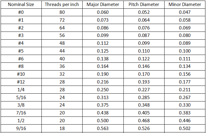
Comprehensive measurement: The measurement reflects the comprehensive index of the relevant parameters of the part. When measuring the thread with a tool microscope, the actual diameter of the thread, the half-angle error of the tooth profile, and the cumulative error of the pitch can be measured separately.
Comprehensive measurement is generally more efficient and more reliable in ensuring the interchangeability of parts. It is often used for the inspection of finished parts. A single measurement can determine the error of each parameter separately and is generally used for process analysis, process inspection, and measurement of specified parameters.
The role of measurement in the processing process is divided into active measurement and passive measurement.
Active measurement: The workpiece is measured during processing, and the result is directly used to control the processing of the part, so as to prevent the occurrence of waste products in time.
Passive measurement: Measurement performed after the workpiece is processed. This kind of measurement can only judge whether the processed parts are qualified or not, and is limited to the detection and rejection of rejects.
According to the state of the part under test in the measurement process, it is divided into static measurement and dynamic measurement.
Static measurement: The measurement is relatively static. Such as a micrometer to measure the diameter.
Dynamic measurement: relative movement between the measured surface and the measuring head during the simulated working state during measurement.
The dynamic measurement method can reflect the situation that the part is close to the use state, which is the development direction of the measurement technology.
Yijin Solution has a history of more than 20 years in the field of machining. It has unique processing methods and precision control in aerospace and aviation and has comprehensive quality system management. We have more than 10 experienced solution solutions engineers and more than 20 Skilled operators, if you have any questions about hardware components, or any problems that need to be resolved can be contacted Yijin Solution, and Yijin Solution will help you complete all this.