


Enclosure drawings often reach the quoting stage with self-clinching nuts placed close to a bend, or with vent patterns that open gaps in the shielding. Each detail like this sends the design back for revision after the first quote, and the project schedule absorbs the extra engineering loop.
Custom sheet metal enclosures are housings cut, bent, and joined from flat sheet to fit a specific board layout, mounting scheme, and service environment around the product. Their cost, fit, and finish quality are largely settled on the drawing well before the first flat blank reaches the shop floor.
Material, wall thickness, bend geometry, hardware placement, and vent design carry the most weight, and each is far easier to adjust on paper than in production.
What Makes a Sheet Metal Enclosure Custom?
A sheet metal enclosure becomes custom when its size, cutouts, and mounting features follow the components inside it rather than a catalog dimension. The drawing fixes every connector opening, PCB standoff, gasket land, and mounting flange, so the housing fits the product instead of the reverse.
Four construction styles cover most custom enclosure work. Each one trades fabrication speed against assembly access and part count:
- U-shape base with cover: a bent channel plus a lid, the quickest style to fabricate; lid seams need close fastener pitch for shielding.
- L-shape pair: two overlapping halves that open two sides for assembly, with more fasteners along the joining edges.
- Folded box: a five-sided box from one blank, with welded, riveted, or tabbed corners; welded corners add finishing labor.
- Chassis and lid: a formed tray that carries the internal hardware under a separate cover, with the highest part count of the four.
The style sets bend count, seam count, and service access, so it comes first in the design sequence. Engineers comparing suppliers can review a list of sheet metal enclosure manufacturers.
Which Materials Suit Custom Sheet Metal Enclosures?
Most custom sheet metal enclosures are built from cold-rolled steel, Aluminum 5052, or Stainless Steel 304. The choice depends on the operating environment, the weight budget, and the finish the enclosure needs.
| Material | Common enclosure uses | Formability | Corrosion behavior | Density | Relative cost |
|---|---|---|---|---|---|
| Cold-rolled steel | Indoor control boxes, rack chassis, industrial panels | Bends readily at small radii | Needs a coating to resist rust | 7.85 g/cm³ | $ |
| Aluminum 5052-H32 | Electronics housings, portable and telecom enclosures | Bends more cleanly than Aluminum 6061-T6 | Holds up indoors and outdoors, including salt air | 2.68 g/cm³ | $$ |
| Stainless Steel 304 | Food, lab, medical, and washdown enclosures | More springback, larger radii | Resists moisture and cleaning agents uncoated | 7.9 g/cm³ | $$$ |
Cold-rolled steel is the lowest-cost option of the three and the stiffest at a given thickness. Bare cold-rolled sheet rusts in humid air, so it needs paint or plating before service. For painted outdoor cabinets, galvanized steel adds a zinc layer under the paint, and galvannealed steel carries a zinc-iron coating that paint grips more readily.
Aluminum 5052 weighs about one third as much as steel at the same thickness, so portable and wall-mounted units are easier to handle and lighter on their mounts. Its H32 temper stays ductile enough to bend at tight radii without cracking.
Aluminum 6061-T6 is stronger, but its heat treatment leaves it less ductile, so it tends to crack on tight bends. Aluminum 5052 is therefore the common grade for custom metal enclosures with formed flanges.
Stainless Steel 304 forms its own chromium oxide film, so bare panels resist moisture and cleaning chemicals without a coating that could chip in washdown. Chlorides from coastal air or bleach-based cleaners can break that film and pit the surface. Stainless Steel 316 adds 2 to 3% molybdenum, which strengthens the film against chlorides, at a higher material cost.
How Thick Should Enclosure Walls Be?
Wall thickness balances stiffness, weight, and hardware compatibility. Specifying it in millimeters rather than gauge avoids confusion because one gauge number maps to different thicknesses in steel and aluminum. For example, a 16-gauge callout means about 1.52 mm in cold-rolled steel, 1.59 mm in stainless steel, and 1.29 mm in aluminum.
Typical starting thicknesses depend on enclosure size and load. Small electronics housings commonly use 1.0 to 1.5 mm sheet, mid-size control enclosures 1.5 to 2.0 mm, and floor cabinets 2.0 to 3.0 mm.
Aluminum needs a thicker wall for the same stiffness, about 1.4 times the steel thickness. A 1.5 mm steel panel therefore becomes about 2.1 mm in aluminum.
Hems or embossed ribs stiffen a flexing panel without moving to a thicker sheet. Extra thickness adds weight and bend force across the whole part.
Hardware also sets a floor, since each self-clinching size lists a minimum sheet thickness. One thickness across a part set, at or above the highest hardware minimum, simplifies nesting and quoting.
How Should Bends Be Handled in Sheet Metal Enclosure Design?
Bend geometry decides whether panels close square, lids seat flush, and box corners form cleanly. The general sheet metal design guidelines cover baseline figures, and enclosures add corner and mating-part details on top of them.
Inside bend radius across a part set
With T as sheet thickness, common starting radii are 1T for cold-rolled steel, 1T to 1.5T for Aluminum 5052-H32, and 1.5T to 2T for Stainless Steel 304. One radius across the enclosure, matched to the fabricator’s standard tooling, lets every bend run on one setup.
A base and lid that share material, thickness, and tooling can share one K-factor, keeping their mating flanges within tolerance. Fabricators often regenerate flat patterns from their own bend tables, so dimensions on the drawing describe the formed part.
Bend relief and box-corner relief
A bend that stops short of the part edge or meets another flange needs relief since the sheet can tear there. A relief width of at least 1T, cut slightly deeper than the bend radius, is a common starting point, with deeper cuts on thicker sheets.
Folded five-sided boxes also need corner relief at each flange joint. Round reliefs suit welded corners, and square or tabbed reliefs suit riveted or cosmetic corners.
Flange length and return flanges
Minimum flange length depends on the V die opening, and about 4T, measured to the outside of the bend, suits most standard tooling. Short return flanges on open edges add stiffness and give cover screws a landing.
How Close Can Holes and Cutouts Sit to Bends and Edges?
Hole and cutout placement controls distortion near bends and the fit of connectors after finishing. The distances below are starting points measured from the bend line or edge, and they shift with material and thickness.
| Feature | Starting minimum distance | Why it matters on an enclosure |
|---|---|---|
| Round hole to edge | 1T, rising to 2T near corners | Keeps thin edges flat during cutting and forming |
| Round hole to bend line | 3T to 4T | Keeps holes round as the bend forms |
| Slot parallel to a bend | 4T | Long slots distort more than round holes near a bend |
| Connector or display cutout to bend | 4T, or a relief cut run into the cutout | Keeps the panel flat so panel-mount parts seat square |
| Self-clinching hardware to bend | Per the hardware maker’s centerline-to-edge data | Bend forces can tilt or loosen pressed inserts |
| Hole to hole | 2T | Keeps the web between holes intact in a thin sheet |
Larger radii widen the bend zone, so holes beside a 2T stainless bend sit about one radius beyond the table figure.
When the title block names ISO 2768 class m, that class sets tolerances for every linear and angular dimension without its own callout, with tighter positional callouts kept for mating holes. Variation across several bends can exceed class m limits, so mating hole patterns sit best on one face or a common datum.
Powder coat builds commonly run 60 to 120 microns per surface, which can take up to 0.24 mm off a hole diameter. The drawing should size clearance holes for the coated condition or mark them for masking, and keep insert mounting holes masked. It should also state whether dimensions apply before or after coating.
Which Hardware Inserts Suit Sheet Metal Enclosures?
Hardware inserts give thin enclosure walls load-bearing threads, studs, and standoffs. The insert type depends on access during assembly, the panel material, and the finishing sequence.
| Insert | Typical enclosure use | Installation | Selection note |
|---|---|---|---|
| Self-clinching nut | Threaded mounts for covers, brackets, and DIN rails | Pressed in from one side; sequence set by the finish | The panel needs to be softer than the insert; stainless panels call for hardened self-clinching types |
| Self-clinching stud | Grounding points and component mounts | Pressed in; sequence set by the finish | Grounding studs stay masked so the bond remains conductive |
| Self-clinching standoff | PCB and module mounting | Pressed in; sequence set by the finish | Height and thread follow the board stack |
| Rivet nut | Threads in closed sections or welded assemblies | Set from one side, often after finishing | Suits panels with no rear access |
| Captive panel screw | Access doors and service panels | Pressed or flared into the panel | Keeps screws attached during field service |
Self-clinching hardware usually goes in after plating or anodizing. With powder coat, it is either pressed in first with its threads masked or fitted after coating.
That sequence belongs on the drawing, with each insert called out by manufacturer part number so that the quote prices the exact hardware. A comparison of sheet metal fastener types covers options beyond these five.
Self-clinching nuts, studs, and standoffs are pressed into the sheet, and the displaced metal can distort a nearby edge and weaken the fastener’s hold. Spacing therefore follows the PennEngineering centerline-to-edge data for each fastener size. Near a bend, that distance is measured to the start of the bend radius since the curved metal beyond it cannot support the fastener.
Installation uses a press, with a punch driving the fastener from one side and an anvil supporting the sheet from the other. After bending, a tall adjacent flange can block the anvil from reaching the hole. In that case, inserts go in while the part is still flat, so their position should also clear the press brake tooling during forming.
Yijin Solution checks insert positions, panel hardness, and finishing sequence during DFM review, before the drawing is quoted.
How Do EMI Shielding and Ventilation Shape an Enclosure?
In sheet metal enclosure design, shielding and cooling pull in opposite directions since every vent is also an opening for electromagnetic interference. Setting both requirements early lets the seam, gasket, and vent details all work together.
EMI shielding at seams and gaskets
Electromagnetic shielding depends on continuous metal-to-metal contact at seams. Overlapping joints hold that contact better than butt joints. Service lids can close the seam with beryllium copper fingers or knitted wire mesh gaskets.
Gasket lands and contact faces stay masked from powder coat. On aluminum, trivalent chromate conversion keeps those faces conductive, while anodizing insulates them.
Vent sizing and airflow
A common starting point keeps the longest dimension of each opening below one twentieth of the shortest wavelength of concern. At 1 GHz, the wavelength is 300 mm, so openings stay near 15 mm or smaller. The same limit applies to seam fastener spacing, pointing to a pitch near 15 mm at 1 GHz or a conductive gasket.
Vent openings leak electromagnetic interference according to their longest dimension rather than their total area. An array of small round holes therefore shields better than long slots with the same open area. Honeycomb vent panels shield better, though they add part cost and need a conductive frame to seal against the enclosure.
Inlets placed low and exhausts placed high support natural convection, and fan cutouts follow the fan’s mounting pattern. Formed louvers sit clear of bends and edges, and face down on vertical panels to shed dripping water. Louver slots usually exceed 15 mm, so louvers suit panels without tight shielding needs.
Which Surface Finish Suits a Custom Enclosure?
Finish choice follows the material, the operating environment, and any conductivity the enclosure needs at seams and grounding points. Each finish adds a specific property, whether corrosion protection, wear resistance, electrical contact, or appearance.
Powder coat is the most common finish for cold-rolled steel and aluminum enclosures. The cured layer seals the metal against moisture, resists chipping in handling, and gives a consistent color specified by the RAL code and gloss level. Because powder coat insulates, seams and grounding points are typically masked to keep metal-to-metal contact for shielding.
Anodizing converts the surface of Aluminum 5052 into a hard oxide layer that resists scratches and corrosion and can take dyed colors. The oxide is also nonconductive, so grounding points need masking. Anodizing is applied after forming, since anodized sheet tends to craze at the bend.
Zinc plating suits cold-rolled steel parts that stay unpainted, such as internal brackets and mounting plates. The zinc corrodes before the steel underneath, and the plated surface stays conductive for grounding and shielding contact.
Stainless Steel 304 resists corrosion without a coating, so its finish is mainly cosmetic. A brushed surface hides fingerprints and light scratches, and bead blasting gives a uniform matte look. Passivation follows either one, clearing iron particles left by tooling so the protective oxide film reforms evenly.
Silkscreen or laser marking adds permanent labels, port legends, and safety markings over the base finish. Masking zones and brushed grain direction go on the drawing next to the finish callout, so the finisher works from one document and adjacent panels match after assembly.
Preparing an Enclosure Drawing for Fabrication
A custom enclosure is easiest to fabricate when its design decisions are made with the fabrication process in view, not after the first quote. Yijin Solution fabricates custom sheet metal enclosures from customer drawings and 3D CAD files, from single prototypes through production runs. Engineers finalizing an enclosure design can send the drawing and model for a free DFM review before requesting a quote.
Custom Sheet Metal Enclosures FAQs
How much does a custom sheet metal enclosure cost?
Custom sheet metal enclosure costs depend on material, bend count, hardware count, finish, and order quantity. Powder coating and insert pressing are priced per part, while programming and setup are spread across the batch, so unit cost falls as quantity rises.
How long does it take to make a custom sheet metal enclosure?
Custom sheet metal enclosure prototypes typically take 3 to 7 days, and production runs usually take 2 to 4 weeks. The timeline moves with part complexity, insert sourcing, and the finish specified.
Is there a minimum order quantity for custom sheet metal enclosures?
Custom sheet metal enclosures have no tooling-driven minimum order quantity since laser cutting needs no hard tooling and press brakes typically run on standard punches and dies. Formed louvers need a turret punch forming tool, so the fabricator confirms louver tooling before quoting.
When is a CNC-machined enclosure chosen over sheet metal?
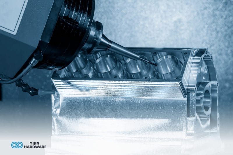
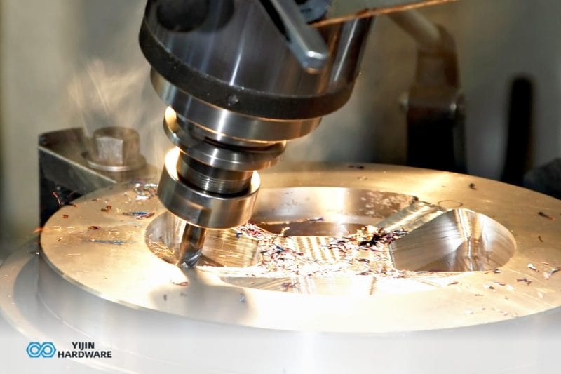
A CNC-machined enclosure suits small housings that need integrated bosses, sealing grooves, or cooling fins cut from solid stock. Sheet metal enclosure fabrication suits medium to large housings, control boxes, and cabinets built from flat walls, flanges, and pressed-in fasteners. It usually costs less per part, and the cost gap widens as panel size grows.
Back to Top: Custom Sheet Metal Enclosures: A Design & Specification Guide



Gavin Yi
Gavin Yi is a distinguished leader in precision manufacturing and CNC technology. As a regular contributor to Modern Machine Shop and American Machinist magazines, he shares expertise on advanced machining processes and Industry 4.0 integration. His research on process optimization has been published in the Journal of Manufacturing Science and Engineering and International Journal of Machine Tools and Manufacture.
Gavin serves on the National Tooling & Machining Association (NTMA) board and frequently presents at the International Manufacturing Technology Show (IMTS). He holds certifications from leading CNC training institutions including Goodwin University’s Advanced Manufacturing program. Under his leadership, Shenzhen Yijin Solution collaborates with DMG Mori and Haas Automation to drive innovation in precision manufacturing.



 English
 Spanish
 German
 French