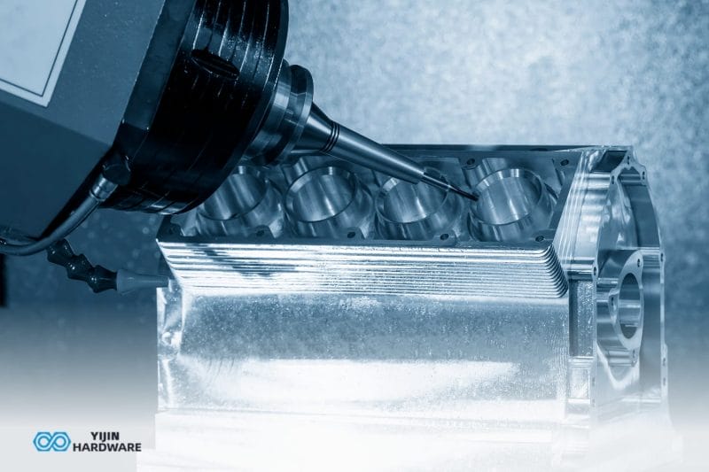


CNC machining refers to the computer-controlled process of manufacturing precision gears using automated machine tools. This advanced manufacturing approach enables the production of complex gear geometries with tolerances as precise as 5-10 micrometers, making it essential for high-performance applications in automotive, aerospace, and industrial equipment sectors.
At Yijin Solution, we specialize in providing reliable CNC machining services for a wide range of gear types, leveraging advanced machining technologies to ensure precision and efficiency. We’ve created this comprehensive guide to examine the various types of gears produced through CNC machining, explore the different manufacturing methods, analyze their comparative advantages, and provide guidance on selecting the right approach for specific applications.
Key Takeaways
- CNC gear machining is a computer‑controlled process that produces precision gears with tolerances as tight as 5–10 µm, enabling complex geometries and consistent quality.
- Gear manufacturing methods range from generation techniques like hobbing, shaping, and the Sunderland/rack‑cutting system for high‑volume precision to cutting approaches (milling, broaching, EDM) for specialized or low‑volume profiles.
- High‑performance gear production relies on advanced CNC equipment — such as high‑speed spindles, grinding machines, and multi‑axis rotary tables — and error‑compensation techniques to meet stringent accuracy and performance demands.
What is CNC Gear Machining?
CNC gear machining is the computer-controlled process of manufacturing precision gears using automated machine tools. This technology enables manufacturers to achieve accuracy levels not possible with manual machining methods, with advanced systems capable of achieving profile form deviation under 10 μm and tooth line basis average error of just 5 μm. Unlike traditional gear manufacturing that relies on change gears and mechanical setups, CNC gear manufacturing uses sophisticated software to control cutting operations with exceptional precision and repeatability.
On many older gear manufacturing machines, you’ll find that change gears are used to “program” the part, with different combinations controlling the synchronization of work and tool spindles. This process requires adjusting hob angles, changing back-off cams, modifying shaping head strokes, and other time-consuming tasks requiring specialized knowledge.
What are Different Types of Gears Made Used CNC Machining?
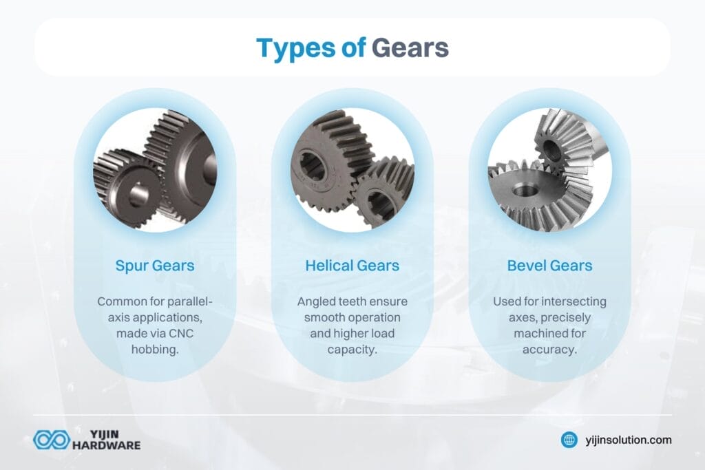
Gears come in several types, each suited for different applications, including spur and helical gears:
- Spur Gears: These are the most common type, used in applications where the axes of the gears are parallel. They are often manufactured using CNC machining processes like hobbing.
- Helical Gears: Similar to spur gears but have angled teeth, providing smoother operation and higher load capacity. They are also commonly produced using CNC machining techniques.
- Bevel Gears: Used when the axes of the gears intersect, often in automotive transmissions. CNC machining helps in producing these gears with precise angles and dimensions.
What are the Different Types of CNC Gear Machining Methods?
CNC gear manufacturing employs various specialized processes, each offering distinct advantages for different applications. The different types of CNC gear machining methods are broadly classified as gear generation and form cutting.
How does Gear Generation Work?
Gear generation removes material through a continuous cutting process that simulates the meshing action of gears. The principle involves generating the tooth profile by simultaneous rotation of the blank and cutting tool. Common gear generation methods include:
What is Gear Hobbing?
Gear hobbing produces gear teeth by rotating a cylindrically shaped cutter called a “hob” (hence the term gear hobbing). The hob can be single-threaded, depending on how many teeth per revolution should be generated.
Spur gears are most often fabricated with this method, although a variety of other gears — like cycloid gears, helical gears, worm gears, ratchets and sprockets — are all made by hobbing. A well-designed hob is critical, especially when cutting a complex geometry, and this process typically does not work for internal gears.
Gear hobbing is one of the most common and efficient gear cutting processes. It uses a rotating cutting tool (hob) to remove material gradually, making it particularly effective for mass production of spur, helical, and worm gears. The method allows for continuous cutting, making it ideal for high-volume manufacturing.
How does Gear Shaping Work?
In this method of gear generation, a cutter and gear blank are connected by gears so that they don’t roll together as the cutter reciprocates. The cutter starts carving its way to the desired depth, then the cutter and gear blank rotates slowly as the gear teeth are cut.
Gear shaping is commonly used for cutting spur gears, herringbone gears, and ratchet gears. This method can be used for other types of gears, but since it uses a cutter that reciprocates the gear shape, it’s often utilized for the gear types mentioned above.
Gear shaping uses a reciprocating cutter that mirrors the shape of the gear being produced. It’s versatile for producing both internal and external gears, and is effective for creating gears with complex profiles. This method is particularly useful for materials that are difficult to machine using other techniques.
What is the Sunderland Method?
Rack-type cutters are one of the main gear manufacturing methods. The gear rack cutting process is also known as the Sunderland Method or the Sunderland System. This method utilizes a gear machine which consists of a rack cutter with rake and clearance angles that creates the tooth profile on a gear blank.
It uses the specific relative motion between the workpiece and the cutter during machining to produce teeth profiles, and is similar to a rack and pinion. The Sunderland Method is designed specifically for producing larger gears with high precision. It employs a rack-type cutter with rake and clearance angles and involves two cutting actions: rough shaping followed by refined finishing.
This method creates teeth of uniform shape, allowing all gears cut by the same cutter to gear correctly with one another. It’s versatile and cost-effective for medium to high-volume production runs.
When Should You Use Form Cutting Methods?
Form cutting generally isn’t preferred because of its limitations — low productivity and poor quality. However, the various form-cutting techniques are useful alternatives for repair and maintenance when necessary.
Gear form cutting uses tools specifically designed to create the gear profile. This approach is relatively limited in use, but is well-suited to creating complex gear geometries when other methods aren’t suitable. Form cutting methods include:
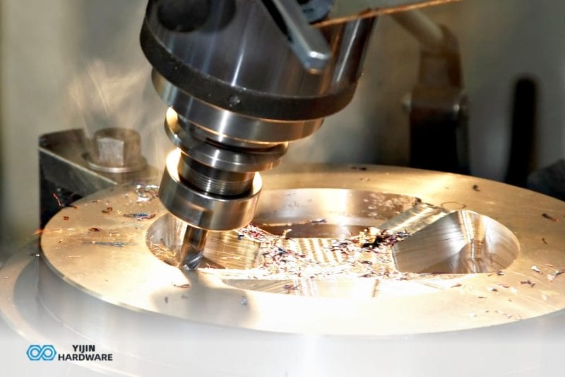
How does Gear Milling Work?
The milling form cutting method is relatively limited in its use, but is well-suited to create complex gear geometries. CNC milling is utilized to machine helical and spur gear wheels for various industries, including automobile transmissions, and hob cutters.
Milling gears is slow because it creates extensive heat transfer to the workpiece, which means that successive teeth should not be milled one right after the other.
Looking for CNC milling China? At Yijin Solution, we specialize in CNC milling for gear manufacturing and other complex part productions, ensuring high precision and performance across industries.
What is Gear Broaching?
This is a quick method that uses a broach (a cutting tool with lots of teeth) that’s specifically designed for gear teeth. Gear broaching can be done on any lathe, milling machine, machining center, or turning machine, but it’s quite expensive because each broach is designed to cut a specific style or size of tooth.
Its price, coupled with the fact it’s one of the fastest gear-cutting processes, is the reason it’s mainly used for high-production parts.
How does Electrical Discharge Machining (EDM) Work for Gears?
EDM is an electromechanical manufacturing process where material is removed from a workpiece by applying a series of current discharges between two electrodes separated by a dielectric bath liquid. Rather than cutting, the spark acts as a ‘cutting tool’ that actually erodes the material instead.
EDM is good at cutting complex geometries of all sizes, even as a gear cutting process, but the process has its limitations. If you don’t have good control and precise programming, it’s easy to damage part surfaces — especially curved teeth profiles that are challenging for CNC programs to execute. But high-quality and intuitive 3D modeling and CAM software — like Feature CAM, Autodesk Fusion, Master CAM, and others — can produce the smooth motion needed to cut curved teeth.
Precision CNC Machining for High-Performance Gears
Precision CNC machining for high-performance gears involves advanced technologies and equipment to ensure that gears meet stringent performance requirements. This includes using high-speed CNC machining equipment and applying compensation techniques to reduce machining principle errors.
The precision machining technology and equipment used in this process are crucial for achieving high-quality gears.
Key Technologies
- Precision Machining Technology and Equipment: Uses advanced CNC gear machine tools to achieve high precision. These tools are designed to minimize errors and ensure consistent quality.
- Compensation Technique of CNC Gear: Helps in reducing multi-source errors during machining. This involves adjusting for distortions and geometry errors to ensure precise gear dimensions.
- Modification Method of High-Performance Gears: Involves optimizing process parameters for improved gear performance. This includes analyzing the gear design and adjusting machining conditions to enhance efficiency.
Machining Equipment
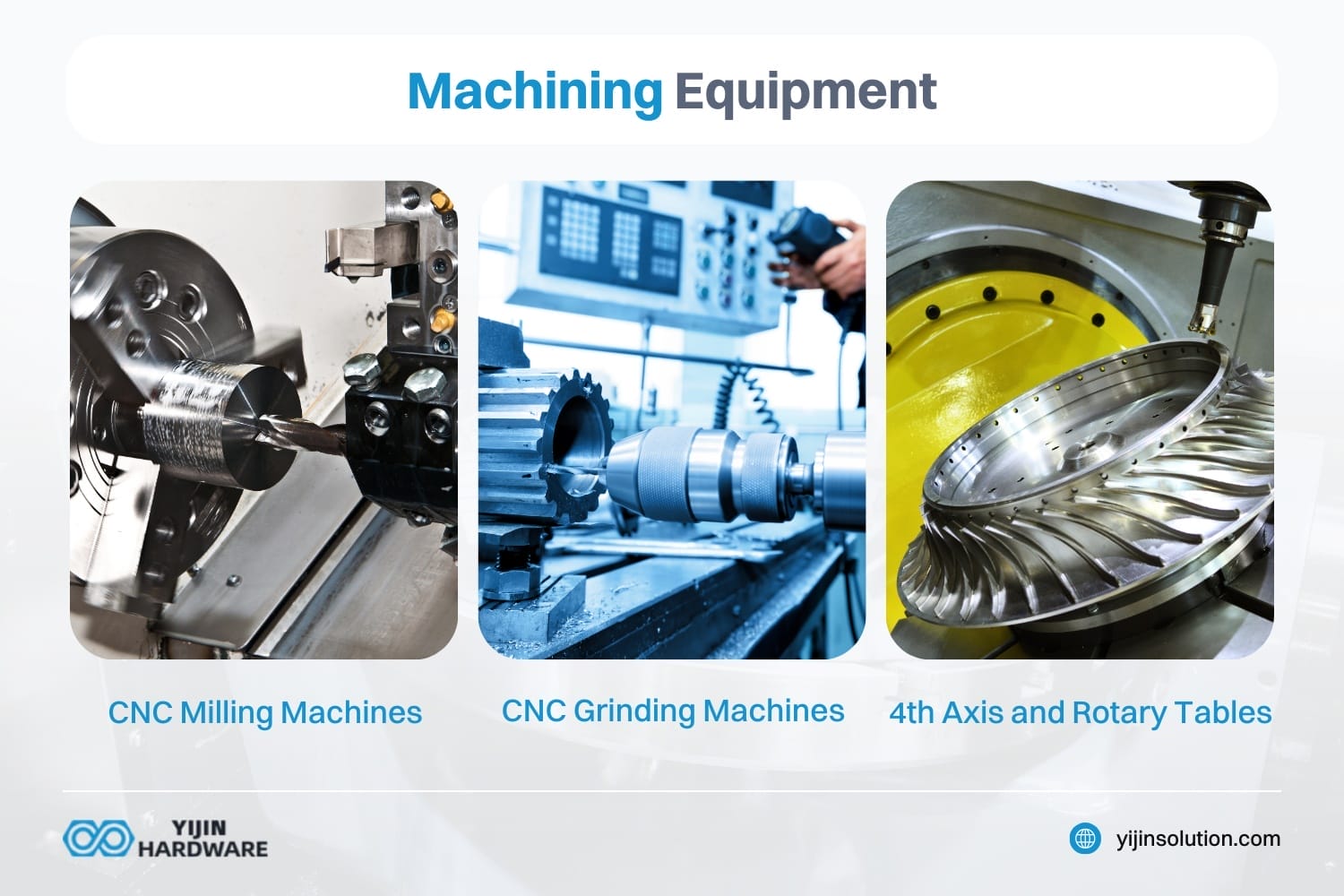
Machining equipment for high-performance gears includes CNC milling machines, CNC grinding machines, and 4th-axis and rotary tables:
- CNC Milling Machines: Equipped with end mills for precise gear cutting. These machines are versatile and can handle complex gear designs.
- CNC Grinding Machines: Essential for achieving high-quality surface finishes. Grinding is often used as a finishing process to refine the gear teeth.
- 4th Axis and Rotary Tables: Used for complex gear designs requiring multiple axes of movement. This allows for precise machining of gears with intricate shapes.
What are Types of Gears Produced by CNC Machining?
Spur gears, helical gears, double helical gears, bevel gears, and worm gears are all produced using CNC machining. We’ve outlined the different types of gears you’ll be able to produce by CNC gear machining.
Spur Gears
Spur gears feature straight teeth mounted on parallel shafts, making them the most commonly used gear type. They excel in low-speed, high-torque applications and offer economical production with high precision. Common applications include electric screwdrivers, washing machines, clocks, and construction equipment.
Helical Gears
Helical gears feature angled teeth that engage gradually, providing smoother and quieter operation than spur gears. Their angled design creates a larger contact area, enabling them to handle heavier loads and higher speeds, making them ideal for automotive transmissions and industrial machinery.
Double Helical (Herringbone) Gears
Double helical gears combine two helical gears with opposite tooth angles, eliminating the axial thrust common in standard helical designs. This configuration provides exceptionally smooth operation with high load capacity, making them ideal for heavy-duty applications in turbines, compressors, and marine propulsion systems.
Bevel Gears
Bevel gears transmit power between intersecting shafts, typically at 90-degree angles. Their conical design with teeth cut at an angle makes them essential for applications requiring direction changes, such as differentials, drill mechanisms, and printing presses. Modern CNC processes enable the production of spiral bevel variations that offer smoother operation and greater load capacity for high-performance applications.
Worm Gears
Worm gear systems consist of a screw-like worm that meshes with a wheel gear, providing high reduction ratios in a compact space. This configuration offers self-locking capabilities and smooth, quiet operation for applications requiring high torque at low speeds. Common applications include conveyor systems, lifts, and steering mechanisms. Their design creates significant friction, making them less efficient but excellent for applications requiring resistance to back-driving.
At Yijin Solution, we specialize in providing reliable CNC machining services for a wide range of gear types. Our expertise in precision CNC machining ensures that our clients receive high-quality gears that meet their specific needs. Contact us today to learn more about our CNC machining capabilities and how we can support your gear manufacturing requirements.
CNC Machining Gears FAQs
What gear cutting processes are available, and when should I choose each?
The most common methods are hobbing for high-volume spur and helical gears, shaping for internal gears or low-volume runs, and grinding for ultra-precise tooth finishes. Select hobbing when you need fast throughput, shaping for complex or small-batch gears, and grinding when tolerances under 5 µm and superior surface quality are required.
What tolerances can modern gear machining achieve?
Standard CNC gear hobbing typically holds to DIN 6 or AGMA 10 grades (±0.02 mm run out), while gear grinders and finishing processes can reach DIN 3 or AGMA 6 (±0.005 mm). Your tolerance choice depends on noise, load capacity and life-cycle requirements.
Which materials are most common for industrial gears?
Alloy steels (e.g., 4140, 8620) dominate in B2B power-transmission applications for their strength and case-hardening ability, while brass, bronze, or engineering plastics serve low-load, low-noise B2C products. Material selection balances load, wear resistance, weight, and cost.
Back to Top: CNC Machining Gears