
Sheet metal design guidelines are the rules that turn a CAD model into a part a fabricator can cut, bend, and form cleanly. The constraints come from physics. Minimum bend radii, hole clearances, flange lengths, and tolerance bands all derive from how a uniform-thickness sheet behaves under the press brake and the laser. Getting them right at the design stage separates a clean first prototype from one that returns with cracks, warps, or dimensions out of spec.
This guide covers the rules that drive most sheet metal cost and quality outcomes, from bend radii and hole placement through to tolerances and hardware inserts. Each rule comes with the reasoning behind it and the trade-offs that drive the limits.
What is Sheet Metal Fabrication?

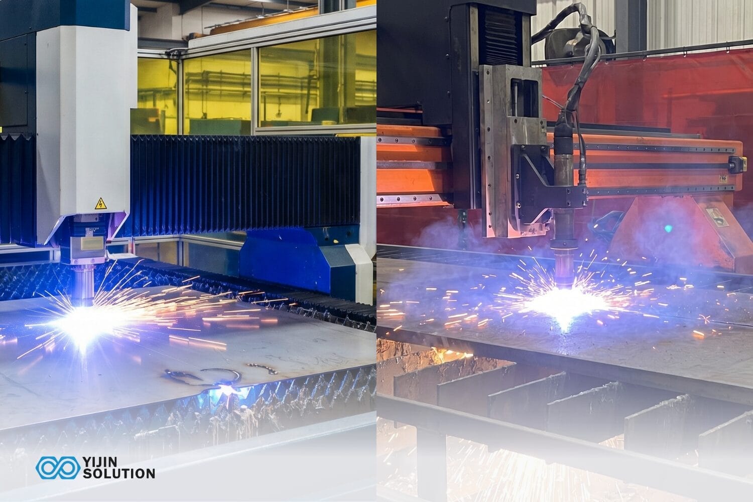
Sheet metal fabrication is the process of cutting and forming a flat metal sheet into a finished part. Two operation categories cover most of the work. Cutting, typically by laser or CNC punch, produces a 2D flat pattern. Forming, typically by press brake bending, turns that flat pattern into the 3D geometry. Every feature is either cut or bent, not built up or machined away mid-plane the way CNC milling or injection molding works.
Because the part starts as a single sheet, it maintains a uniform thickness throughout. That uniform thickness is the defining constraint of the process. The flat pattern is what the fabricator actually cuts, so every bend must be compensated for in the CAD model using bend allowance calculations.
Bending stretches the outer fibers and compresses the inner fibers of the material. This is why minimum bend radii, minimum flange lengths, and relief cuts exist as design constraints. Understanding these constraints before locking a design saves time, tooling cost, and scrap.
Sheet Metal Design Guidelines at a Glance
The table below summarizes the key design parameters covered in detail throughout this guide. These are starting-point guidelines, not fixed universal rules. Actual values depend on material type, thickness, part geometry, and fabricator capability.
| Design parameter | Guideline / typical rule |
|---|---|
| Minimum inside bend radius | ≥1× material thickness for most metals; varies by ductility |
| Consistent bend radii | Use a single radius across the part to reduce tool changes |
| Minimum hole diameter, punching | ≥ material thickness for punched holes |
| Hole-to-edge clearance | ≥1× material thickness as a starting guideline |
| Hole-to-bend clearance | ≥3 to 4× material thickness; confirm with fabricator |
| Minimum flange length | ≥4× material thickness for press brake forming |
| Tolerances | Standard ±0.30 mm; precision ±0.10 mm; varies with geometry and feature type |
| Uniform wall thickness | Avoid sudden section changes near bends or punched features |
| Grain direction | Orient critical bends perpendicular to the rolling direction |
| Weld access | Allow clearance for weld gun or fixture access at joints |
Sheet Metal Design Rules

Each rule below pairs a starting-point value with the physics or process reasoning that justifies it. Actual capability depends on the material, the fabricator’s tooling, and the geometry of the specific part.
Material selection and thickness
Material choice shapes every downstream design decision. The most common sheet metal materials are mild steel, stainless steel, aluminum, and copper alloys. Each behaves differently during cutting and forming. Mild steel bends predictably and is the easiest to form. Stainless steel work-hardens during bending, meaning repeated forming operations increase material hardness and brittleness near the bend zone. Aluminum 5052 bends more cleanly at tight radii than Aluminum 6061-T6, which is slightly brittle and may require a larger bend radius to prevent cracking.
Material thickness is the reference dimension for most other design rules in this guide. Minimum bend radii, hole-to-edge distances, and flange lengths are all expressed as multiples of the material thickness. A 1.0 mm aluminum sheet and a 3.0 mm stainless steel plate follow the same proportional rules, but the absolute dimensions differ significantly.
Material grade should match the application requirements. Stainless Steel 316L is common in medical device enclosures for corrosion resistance. Aluminum 5052 is a standard sheet for electronics enclosures, when formability matters more than absolute strength.
Bend radius minimums
The minimum inside bend radius for most metals sits at least 1× the material thickness as a starting point. This is not a fixed rule, because the actual minimum depends on the material’s ductility, temper, grain direction, and the forming method.
Mild steel at standard thickness bends comfortably at 1× thickness. Stainless steel and higher-strength alloys may need 1.5 to 2× thickness to avoid cracking.
Bending below the minimum radius causes material thinning on the outside of the bend, where the outer fibers stretch beyond their elongation limit. Cracks initiate at the bend line surface and propagate inward. Springback also increases at smaller radii, making the final bend angle harder to control. For Aluminum 6061-T6, which has lower ductility than most forming-grade alloys, the recommended starting point is 2× thickness or more.
Designing all bends on a part to the same radius reduces tool changes on the press brake. Every different radius requires a different punch, which adds setup time and cost. A single bend radius across the part is the simplest setup.
Hole placement and sizing
Three hole-related rules prevent the most common fabrication failures in sheet metal: minimum hole diameter, hole-to-edge distance, and hole-to-bend distance.
For punched holes, the minimum diameter should be at least equal to the material thickness. A 1.5 mm thick sheet needs holes no smaller than 1.5 mm in diameter when punching. Laser cutting can achieve smaller diameters, but quality degrades at very small sizes, especially on thicker sheets where the kerf width affects the hole geometry.
Holes placed too close to an edge cause material deformation during punching. The edge bulges or tears because there is not enough material to resist the shearing force. A minimum of 1× material thickness from the hole edge to the part edge is a common starting guideline.
Holes placed too close to a bend zone distort during forming. The bending force redistributes through the nearby hole, pulling it into an oval shape or cracking the material between the hole and the bend line. A clearance of 3 to 4× material thickness between the hole edge and the start of the bend zone is a typical starting point. The exact value should be confirmed with the fabricator, since it depends on the material, the bend radius, and the tooling setup.
Flange lengths and hem features
Flanges that are too short create two problems. The press brake tooling cannot grip the material securely, and the short flange springs back unpredictably after forming. A minimum flange length of roughly 4× the material thickness is a common starting point for standard press brake work. Below that threshold, the fabricator may need special tooling or a different forming approach, both of which add cost.
Designing parts with multiple different flange depths adds setup complexity, since each unique depth may require its own setup or a different tool combination. Standardizing flange heights across a part keeps setup count down.
Hem features, in which the sheet metal is folded back on itself, add edge rigidity and create a smooth, safe edge. A closed hem folds the material completely flat against itself. An open hem leaves a small gap. Closed hems are more rigid but require more forming force and may crack on harder materials.
Wall thickness consistency
Sheet metal parts start as a uniform-thickness sheet, and the design challenge is keeping material behavior consistent throughout. Sudden changes in section, such as a punched relief cut positioned directly adjacent to a bend, alter the local stress distribution. The result can be cracking, warping, or dimensional inconsistency in the formed part.
Features that effectively change local thickness behavior include embosses, ribs, and louvers. These need careful dimensioning and positioning relative to bends and edges. An emboss placed too close to a bend line competes with the bending force and can distort both the emboss and the bend. Consistent thickness across a part simplifies tooling setup, reduces scrap rates, and lowers per-part cost.
Achievable tolerances
Tolerances on sheet metal parts break into two categories: cut-feature tolerances and formed-feature tolerances. These differ, and designers who transition from CNC machining to sheet metal often underestimate how much forming operations widen the tolerance band.
Laser-cut features (holes, slots, profiles) can hold relatively tight tolerances because the cutting process is CNC-controlled with minimal mechanical distortion. Formed features (bends, flanges, compound geometries) introduce variables such as springback, material grain effects, and tooling wear that widen the achievable tolerance range.
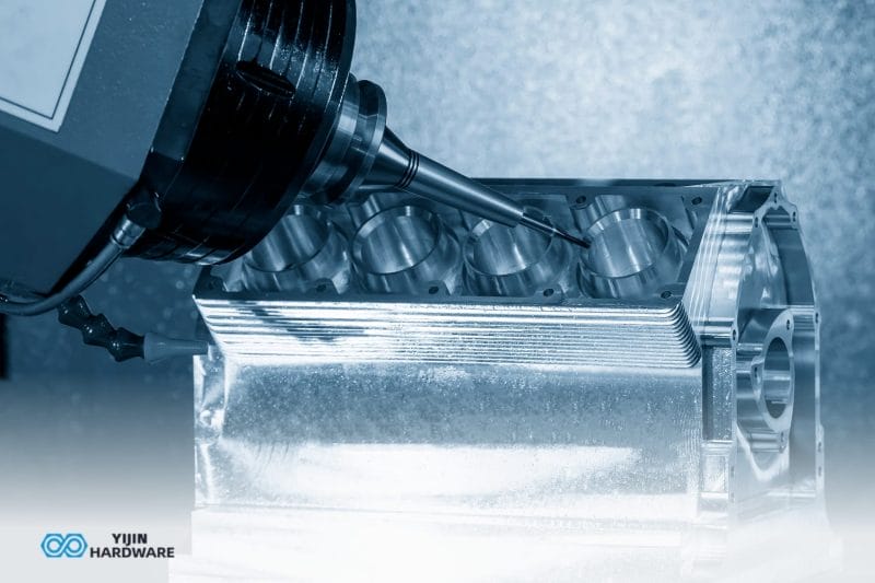
Typical sheet metal fabrication achieves precision tolerances around ±0.10 mm and standard tolerances around ±0.30 mm. These are reference figures, not universal standards. Actual achievable tolerances depend on part geometry, material, and feature type. If a design requires tighter tolerances on specific mating features, secondary CNC machining of those features after forming is a common and practical hybrid approach.
Bend allowance and K-factor
When sheet metal bends, the outer surface stretches and the inner surface compresses. Somewhere between those two surfaces sits the neutral axis, a line inside the material that stays at its original length. The flat pattern your CAD software exports is calculated from this neutral axis, and bend allowance is the term for the arc length of the bend measured along it.
K-factor is the ratio that locates the neutral axis within the sheet thickness. Typical values range from 0.25 to 0.50. Softer materials and sharper bends push the K-factor lower. Harder materials and larger radii push it higher. If your CAD sheet metal module uses an assumed K-factor that differs from the actual value for your material and tooling, the formed part will be dimensionally off. The fix is straightforward: use your fabricator’s recommended K-factor values, or at minimum confirm that your CAD software’s defaults match the shop’s actual forming conditions.
Relief cuts and springback
When a bend ends partway along an edge rather than running the full width of the sheet, stress concentrates at the termination point of the bend line. Without intervention, this stress concentration tears the material. A relief cut, a small slot or notch placed at the end of the bend line, releases that stress and lets the bend form cleanly. The width of the relief should be at least equal to the material thickness.
Relief cuts should be designed in for any bend that does not extend fully across the part, any bend that runs near a cutout, and any hardened material with an elevated cracking risk. Omitting relief cuts is one of the more common causes of first-article rejection.
Springback is the tendency of metal to relax slightly toward its original flat shape after the press brake releases it. The fabricator compensates by overbending. As a designer, you specify the final bend angle you need, not the overbend angle. Springback compensation belongs to the fabricator and the press brake setup, not to the design specification.
Springback is more pronounced in harder, higher-tensile materials such as stainless steel and spring steel, and with larger bend radii. Material choice influences expected bend accuracy, and design tolerances should reflect that.
Hardware inserts and welded joints
Thin sheet metal often cannot hold reliable threads on its own. Self-clinching hardware, commonly called PEM inserts, solves this by press-fitting threaded nuts, studs, or standoffs into the sheet. Clearance holes should be designed to match the hardware manufacturer’s specification exactly.
Installation sequence matters more than most designers expect. Some inserts go in before forming, some after. Some go in before surface finishing, some after. Getting the sequence wrong can mean an insert that interferes with a bend, or a surface finish that prevents proper clinching. The fabricator confirms the correct sequence during the DFM review.
For welded joints, clearance for the weld gun or fixture access is a design requirement, not an afterthought. Lap joints, butt joints, and corner joints each need different minimum clearances, and the welding setup should be sketched before the joint geometry is finalized.
Many sheet metal assemblies combine both threaded inserts and welding. Inserts and mechanical fasteners are faster and lower cost for low-volume production. Welding produces more rigid joints for structural assemblies.
Feature proximity, grain direction, and part nesting
Design for manufacturability in sheet metal means aligning design intent with what the fabrication process can actually produce at reasonable cost. A design that looks clean in CAD may not be cost-effective, or even feasible, without adjustments to feature placement and orientation.
Feature proximity to bends is one of the most common DFM issues. Holes, slots, and cutouts placed within the bend deformation zone will distort during forming. The required clearance depends on material thickness, bend radius, and feature size, which is why a fabricator review before design lock catches problems that rules of thumb alone may miss.
Grain direction affects bending behavior. Sheet metal has a rolling direction from the mill, and bending perpendicular to the grain allows tighter radii with a lower cracking risk than bending parallel to it. For critical bends, perpendicular orientation to the grain is good practice.
Part nesting, how flat patterns are arranged on the sheet for cutting, directly affects material yield and cost. Designs with irregular shapes or features that prevent close nesting waste more raw material. A bend-radius issue or a nesting inefficiency caught during DFM review is corrected with a CAD edit. The same issue caught after first-article tooling is cut requires new material, new tooling time, and rework labor.
How Fabrication Method Affects Your Sheet Metal Design
The choice between laser cutting and CNC punching for flat features changes which design rules apply. Laser cutting handles complex contours and small features well, with kerf widths as narrow as 0.1 to 0.3 mm on thin sheets. CNC punching is faster for high volumes of standard hole patterns but has larger minimum feature sizes and leaves different edge characteristics. Hole diameter minimums are lower for laser cutting, but very small laser-cut holes on thick material may have tapered walls.
Press brake forming imposes its own constraints: minimum flange lengths are set by the tooling, bend relief requirements depend on the bend geometry, and achievable bend angles are limited by the die and punch combination. Understanding which cutting and forming methods the fabricator will use helps explain why the design rules in this guide exist, and which ones apply to a specific part.
Get a Free DFM Review Before Fabrication
In sheet metal, the difference between a clean first article and a rework cycle usually comes down to whether the design accounts for forming behavior, not just cut geometry. Yijin Solution’s DFM review reads a sheet metal file the way the press brake setup will, against the actual tooling and material lot that will run the job.
Send your sheet metal design for a DFM review and quote within 24 hours.
Sheet Metal Design Guidelines FAQs
The questions below come up most often during sheet metal DFM reviews.
What is the minimum bend radius for sheet metal?
The minimum inside bend radius is at least 1× the material thickness as a starting point for most metals. Mild steel bends comfortably at that ratio. Stainless steel may need 1.5 to 2× thickness, and Aluminum 6061-T6 may need 2× or more because of its lower ductility. The actual minimum also depends on grain direction, forming method, and tooling. Confirm with the fabricator before locking any radius below 1× thickness.
How close can a hole be to a bend in sheet metal?
A hole should be at least 3 to 4× the material thickness away from the start of the bend zone. Holes placed closer than this distort during forming, because the bending force pulls the material around the hole unevenly. The exact minimum depends on the material, thickness, and bend radius, and is best confirmed with the fabricator based on the specific design.
What tolerances can sheet metal fabrication achieve?
Sheet metal tolerances depend on whether the feature is cut or formed. Laser-cut features hold tighter tolerances than formed features. Precision tolerances of ±0.10 mm and standard tolerances of ±0.30 mm are achievable, depending on geometry and feature type. For features that need tighter tolerances, secondary CNC machining after forming is a practical option.
What materials work best for sheet metal fabrication?
Mild steel is the most widely used sheet metal material because of its formability, weldability, and cost. Stainless steel is standard for corrosion-resistant applications such as medical enclosures and food equipment. Aluminum 5052 is widely used in electronics enclosures and parts that need good formability. Material selection depends on the application, required surface finish, and operating environment.
How does a DFM review improve sheet metal parts?
A DFM review identifies design issues before tooling is cut and material is committed. Problems such as insufficient bend relief, holes too close to bends, or flange lengths below the forming minimum are caught early, which saves both time and cost. A free DFM review as part of the quoting process flags manufacturability risks and suggests adjustments before production begins.
Back to Top: Sheet Metal Design Guidelines: Rules, Tips & DFM Best Practices