
Design for CNC machining is the practice of shaping a part in CAD so that it matches what cutting tools can actually produce. The constraints come from physics: rotating cylindrical tools have minimum corner radii, limited reach, and rising deflection at depth. Designs that account for these constraints in the CAD stage reduce per-part cost and lead time before any quote is issued. Designs that do not tend to lose time on requotes and rework cycles after the first prototype.
This guide covers the design rules with the largest impact on CNC machining cost, from corner radii and wall thickness through to material selection and fixturing. Each rule comes with specific numbers and the cost logic behind it.
What is the CNC Machining Process?
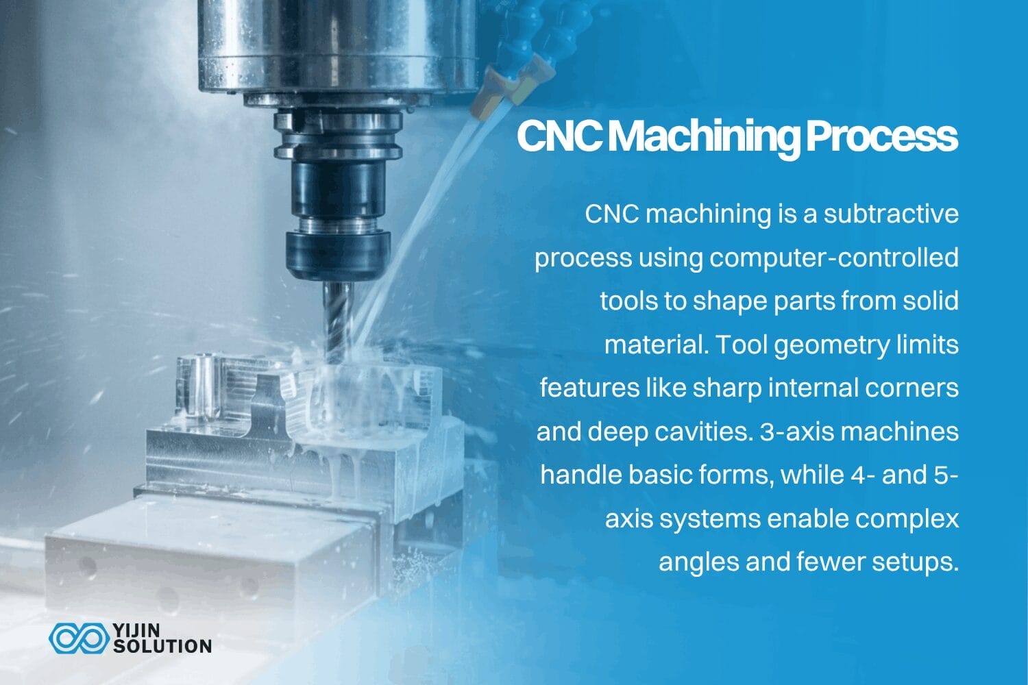
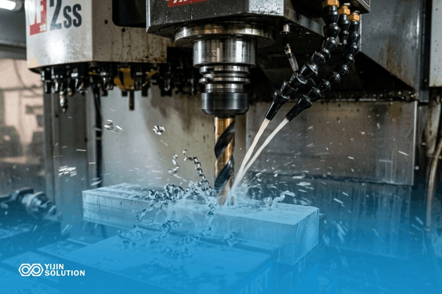
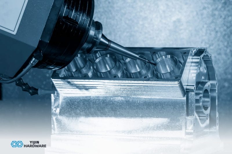
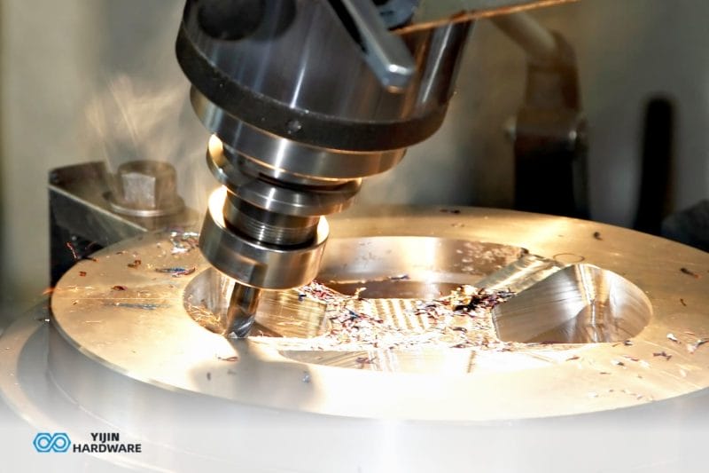
CNC machining is a subtractive manufacturing process. Computer-controlled cutting tools remove material from a solid block of metal or plastic to produce a finished part that matches a CAD model. The design constraints below come directly from how CNC-Bearbeitung physically works.
Cutting tools are cylindrical and have limited reach. That means certain geometries are difficult or impossible to produce: true 90-degree internal corners, deep narrow cavities, and features that sit outside a straight-line toolpath.
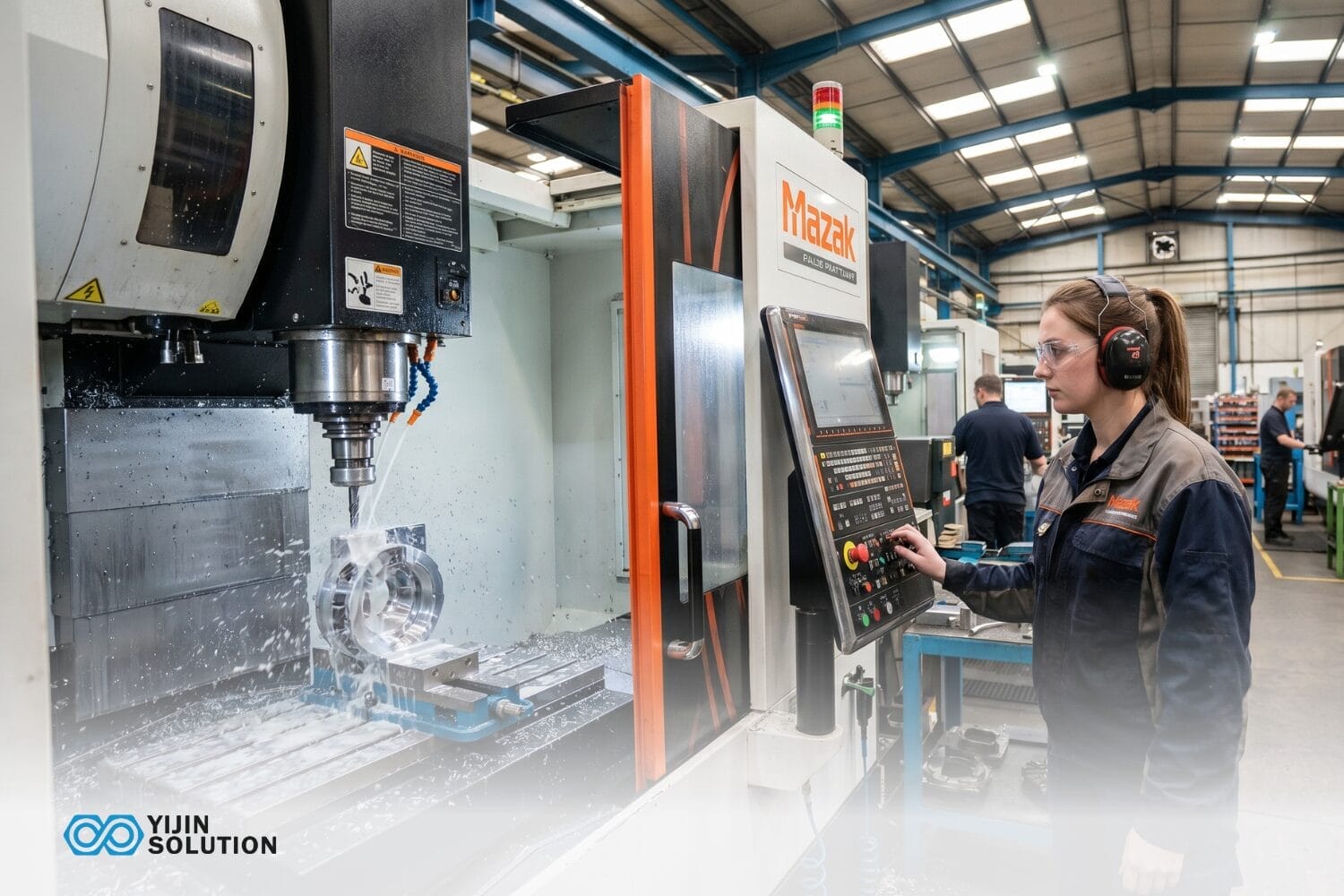
3-axis machines handle most prismatic geometry. 4-axis and 5-axis machines add rotational axes to reach compound angles and reduce the number of setups on complex parts.
CNC Machining Design Guidelines, at a Glance
The table below summarizes the core design parameters for CNC machined parts. Use it as a quick reference before sending a drawing to a machine shop. Each parameter is covered in detail in the sections that follow.
| Design parameter | General guideline | Why it matters |
|---|---|---|
| Internal corner radii | Minimum R0.5 mm; at least 1/3 of cavity depth | Tool diameter sets the minimum achievable radius; undersized corners require slower, smaller tools or EDM |
| Wandstärke | Minimum 0.8 mm for metals, 1.5 mm for plastics; 1.5 mm or more recommended | Thin walls cause chatter and deflection, which degrade Oberflächengüte and dimensional accuracy |
| Hole depth-to-diameter | Standard: 4:1 or less; deep drilling up to 10:1 | Beyond standard ratios, chip evacuation becomes difficult and tool deflection increases cost |
| Thread depth | 2 to 3 times thread diameter | Deeper threads add machining time; shorter threads risk insufficient pull-out strength |
| Unterschneidet | Avoid when not functionally required; use standard T-slot or dovetail profiles if needed | Each undercut adds a tool change and often a fixture change |
| Toleranzen | Standard: ±0.1 mm; precision: ±0.01 to 0.05 mm | Tighter tolerances require slower feeds, more passes, and higher inspection cost |
| Oberflächengüte | As-machined Ra 1.6 to 3.2 µm; finish passes Ra 0.4 to 0.8 µm | Secondary finishing affects both dimensions and surface spec |
| Part fixturing | Design stable 3-point datum surfaces | Parts without clear datums require custom fixtures, adding cost and lead time |
| Tool access | All features reachable within 4 setups or fewer | Each additional setup increases machining time and introduces positional error |
| Standard feature sizes | Use metric or imperial drill sizes and standard threads | Non-standard sizes force custom tooling, adding procurement time and per-part cost |
What Are the Key Design Guidelines for CNC Machining?
The sections below detail the design rules summarized in the table above. Each rule includes the underlying physics, specific numerical guidelines, and the cost trade-offs that drive the limits.
Internal corner radii
Undersized corners are the most common DFM error on CNC drawings, and the cost they add is easy to avoid. Cutting tools are cylindrical. They cannot produce a true sharp internal corner. The smallest radius a tool can produce equals the tool’s own radius, and smaller tools run slower, deflect more, and wear faster.
The working rule: internal corner radius should be at least one-third of the pocket depth, with a recommended minimum of R0.5 mm. A 12 mm deep pocket, for example, needs at least a 4 mm radius in its corners. Tighter radii force the shop to step down to a smaller-diameter endmill, which means more passes at lower feed rates. In some cases, the only option is EDM, which adds both cost and lead time.
Every internal corner should carry an explicit radius callout on the drawing. An undimensioned corner forces the machinist to interpret the geometry, and the resulting radius may not match assembly requirements.
Wandstärke
Thin walls vibrate during cutting. The technical term is chatter, and it leaves a rough, wavy surface finish while pulling dimensions out of spec. Minimum recommended wall thickness for metals is 0.8 mm, though 1.5 mm or more is preferred for structural rigidity. Engineering plastics need at least 1.5 mm because they deflect more readily under tool pressure.
These are guidelines, not fixed limits. Achievable minimums depend on material stiffness, wall height, and how the part is fixtured. A 0.8 mm aluminum wall that is 5 mm tall behaves differently from one that is 50 mm tall. The taller wall has far more deflection, and machining it cleanly takes lighter cuts and more time.
If a design requires thin walls, ribs or gussets on the non-cosmetic side often solve the problem. Small geometry changes can stiffen the part enough to machine cleanly without adding significant weight.
Hole depth and thread design
Standard depth-to-diameter ratio for drilled holes is 4:1 or less. A 6 mm hole drilled to 24 mm is straightforward. Beyond that ratio, chip evacuation becomes a problem. The drill has to peck in and out to clear chips, which adds cycle time. Deep drilling up to 10:1 is possible with gun drills or high-pressure coolant, but the per-feature cost rises significantly.
For threaded holes, minimum engagement depth is 2 to 3 times the thread diameter. An M6 thread should engage at least 12 to 18 mm for a full-strength connection. Going deeper adds machining time without proportional strength gain. Going shorter risks the fastener pulling out under load.
Through-holes are cheaper than blind holes when the design allows them. Blind holes require careful depth control, and tapping a blind hole at depth requires a bottoming tap, an additional tool change. Counterbores and countersinks should use standard sizes that match stock tooling. A non-standard counterbore diameter forces the shop to interpolate the feature with an endmill instead of plunging with a purpose-built tool.
Hinterschneidungen und vertiefte Merkmale
An undercut is any feature that a straight-line tool path cannot reach from the setup direction. T-slots, O-ring grooves on internal bores, and dovetails all qualify. Each undercut typically requires a dedicated tool, sometimes a specialty form cutter, and often an additional fixture orientation.
Standard T-slot and dovetail cutters come in limited sizes. If the undercut matches a standard profile, the machining cost stays reasonable. Non-standard undercut profiles may require custom-ground tools, which adds procurement time and expense. On a multi-axis machine, some undercuts can be reached by tilting the spindle, but this raises the per-hour rate.
Each undercut benefits from a flag during design review and a check on whether the feature is functionally necessary. If an O-ring groove can be moved to an external surface, the tool access problem disappears entirely.
Toleranzen
Tolerance drives cost on a steep curve. Standard CNC machining achieves ±0.1 mm for most features without special effort. Precision machining reaches ±0.05 mm. High-precision work, down to ±0.01 mm, requires slower feed rates, additional finishing passes, controlled thermal conditions, and higher inspection burden. ASME Y14.5 defines the standard framework for geometric dimensioning and tolerancing that governs how these callouts appear on engineering drawings.
A ±0.01 mm tolerance band is achievable on properly fixtured parts in stable materials such as Aluminum 6061 or brass. It is not a universal capability. Achievable tolerance depends on part geometry, material behavior, feature size, and fixturing strategy.
Tight tolerances should be reserved for critical mating surfaces, datum features, and functional interfaces. Blanket-tolerancing an entire drawing to ±0.05 mm when only two bores actually need it can add 20 to 40 percent to machining time without any functional benefit. General tolerances cover non-critical features, while precision callouts handle the dimensions that matter to assembly and performance.
Oberflächengüte
Standard as-machined surface finish on a CNC milled part falls between Ra 1.6 and 3.2 µm. Finish passes with reduced stepover and controlled tool engagement can bring that down to Ra 0.4 to 0.8 µm, though cycle time increases accordingly. Surface roughness is measured per ISO 4287, which defines the Ra, Rz, and Rmax parameters used on most engineering drawings.
When the application requires it, secondary finishing processes such as anodizing, grinding, polishing, or bead blasting can improve both appearance and functional performance. Each of these processes interacts with the primary machined dimensions.
Anodizing is a common example. Type II sulfuric acid anodizing adds roughly 5 to 18 µm of surface build-up per side, depending on coating thickness and alloy. On a feature toleranced to ±0.02 mm, that dimensional shift matters. Hardcoat anodizing, or Type III, adds substantially more, potentially 25 to 50 µm per surface.
If a part will be anodized, the drawing should specify whether tolerances apply before or after coating, and the machined dimensions should account for the expected build-up. Surface finish and coating allowances belong in the design conversation, not the post-machining one.
Part setup and fixturing considerations
Every time a part is unloaded, flipped, and re-fixtured, two things happen: labor time increases and a small positional error is introduced. The goal in DFM is to reduce the number of setups required to machine the part.
At least one flat, stable reference surface should appear on every part. This datum surface is what the fixture clamps against. Without clear datum geometry, the shop has to build a custom fixture, which adds cost and lead time. Three-point contact is the minimum for stable fixturing, and parts with curved or irregular base geometry are harder to locate accurately.
5-axis machining can often consolidate a 4-setup 3-axis job into one or two setups. The per-hour rate is higher, but the total cost frequently comes out lower for complex parts because setup time, fixturing cost, and positional error are all reduced.
Material selection and its effect on machinability
Material choice affects tool life, cycle time, achievable surface finish, and per-part cost. Not all metals machine the same way, and the differences are large enough to change the economics of a project.
| Material | Bearbeitbarkeit | Typical application |
|---|---|---|
| Aluminium 6061-T6 | Excellent, high cutting speeds, long tool life | Structural parts, enclosures, heat sinks |
| Messing C360 | Excellent, free-cutting, minimal burr | Electrical connectors, fittings, valve bodies |
| Mild Steel 1018 | Good, moderate speeds | Brackets, shafts, structural components |
| Rostfreier Stahl 304 | Moderate, work-hardens during cutting | Food processing, medical, marine hardware |
| Stainless Steel 316L | Moderate to difficult, gummy chip formation | Chemical processing, surgical instruments |
| Titanium Ti-6Al-4V | Difficult, low thermal conductivity | Aerospace structural, medical implants |
| PEEK | Good with sharp tools, melts if overheated | Medical devices, semiconductor fixtures |
Harder and more abrasive materials require slower cutting speeds and more frequent tool changes. A titanium part might take three to five times longer to machine than an equivalent aluminum part, with higher tooling cost on top. When the design allows material flexibility, choosing a more machinable alloy reduces per-part cost without changing the manufacturing process. For parts whose geometry favors forming over cutting, Blechfertigung is often the more economical route.
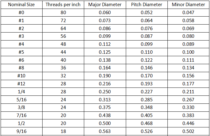
Use standard feature sizes
Designing to standard drill sizes, thread sizes, and counterbore diameters is one of the most effective ways to reduce per-part cost without changing the design’s function.
A 3 mm hole is a one-tool operation using a stock drill bit. A 3.15 mm hole forces the shop to interpolate the diameter with an endmill, which is slower and more expensive. The same logic applies to threads: standard metric sizes such as M3, M4, M5, M6, M8, and M10 use off-the-shelf taps. Non-standard thread pitches require dedicated taps or thread-milling programs, both of which add time and tooling procurement.
Counterbores and countersinks should match the fastener standard being used, whether DIN, ISO, or ANSI. Pulling one non-standard size into a drawing can add a custom-tool procurement step to the entire job. If a non-standard size cannot be avoided, it should be flagged in the drawing notes so the shop can quote the tooling separately rather than absorbing the cost into the part price.
Tool access and setup count
Every feature on a part should be reachable by a straight-line tool path from at least one of six principal directions: top, bottom, front, back, left, right. Features that sit outside these access directions require 5-axis machining or a secondary operation.
Setup count matters because every re-fixture introduces labor time and a small positional error between features machined in different orientations. A part that machines in one or two setups on a 3-axis machine carries a meaningful cost advantage over a multi-setup design. For complex geometry, a single 5-axis setup may cost more per hour but less in total, because it eliminates fixture changes and the cumulative positional error that comes with them.
Tool reach also affects accuracy. Deep pockets and narrow slots require extended-reach endmills, which deflect more under cutting forces and reduce achievable accuracy. As a general guideline, cavity depth should not exceed four times the feature width. Deeper features are possible but require slower feeds and lighter cuts to control deflection.
Text, engraving, and part markings
Engraving cuts characters into the surface. Embossing removes material around each character to leave raised lettering. Engraved text is significantly cheaper to machine, and the cycle time gap widens on parts with long serial numbers or detailed logos.
Sans-serif typefaces at 20-point size or larger machine cleanly. Thin strokes and serifs are difficult to produce at small sizes. If the part will be anodized, laser marking is often a better option than engraving. Laser marking on anodized aluminum produces high-contrast, permanent text without adding machining time.
Text specifications should appear on the drawing, not only in the CAD model. Location, font, character height, and engraving depth all belong as dimensioned callouts. Shops that receive a solid model with embedded text and no drawing callout may interpret the text as decorative rather than functional, which is how markings get missed.
What Design Mistakes Most Often Drive Up CNC Machining Costs?
The design rules above cover feature-level guidance. The mistakes below are drawing-level and process-level issues that sit outside any single feature, and a quick self-audit before sending a drawing to a machine shop catches the ones that most often trigger requotes or rework.
- Missing or conflicting GD&T callouts. Ambiguous geometric dimensioning creates interpretation differences between the designer and the machinist. A single datum reference frame and consistent feature control frames prevent most issues. If the shop has to call and ask what a tolerance means, the drawing was not clear enough.
- Designing to material properties without confirming machinability. A material may have the right tensile strength and corrosion resistance for the application, but if it work-hardens aggressively or produces long, stringy chips, machining costs rise. Machinability ratings should be checked before a material selection is locked in.
- Drawing notes that conflict with the CAD model. When a corner radius, hole size, or thread spec differs between the 2D drawing and the 3D file, the shop has to stop and ask which is correct. Clear hierarchy on the drawing (“drawing governs” as a standard note) prevents most of these delays.
Get a DFM Review Before CNC Production
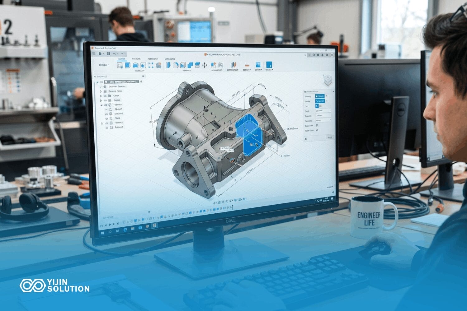
Most CNC cost is locked in during the CAD stage, well before machining begins, which makes the design phase the right place to optimize.
Yijin Solution’s free DFM review evaluates each feature against real tooling, material, and fixturing constraints, returning specific design recommendations within 24 hours of CAD file upload.
Upload your CAD file for a feature-level manufacturability check and a quote.
FAQs on A Practical Design Guide for CNC Machining
These questions come up most often during DFM review and quoting.
What is the minimum wall thickness for CNC-machined metal parts?
The practical minimum for metals is 0.8 mm, with 1.5 mm or more recommended for rigidity. Achievable minimums depend on the specific material, wall height, and how the part is fixtured, not just machine capability. Aluminium-Legierungen tolerate thinner walls more readily than stainless steel because they are stiffer relative to cutting forces. Tall, unsupported walls require lighter cuts regardless of material, which adds cycle time.
How do I reduce the cost of CNC machined parts through design?
Four areas matter most: tolerance management, standard feature sizes, setup count, and DFM review. Apply tight tolerances only where functionally required. Specify standard drill and thread sizes to avoid custom tooling. Design geometry that machines in as few setups as possible. A free DFM review identifies cost-reduction opportunities before the first quote is issued, and is the single most effective step toward lower per-part cost.
What tolerances can CNC machining achieve?
Standard CNC machining holds ±0.1 mm. Precision work reaches ±0.05 mm, and high-precision machining can hold ±0.01 mm under controlled conditions. Tighter tolerances are not free. Each step toward ±0.01 mm increases cycle time, requires additional finishing passes, and raises inspection cost. The cost-effective approach is to specify tight tolerances only on features where they actually matter, such as bores that mate with bearings or datum surfaces that define alignment.
What is the difference between CNC milling and CNC turning for design purposes?
CNC milling removes material from a stationary workpiece using a rotating tool. It suits prismatic parts, pockets, and complex 3D surfaces. CNC turning rotates the workpiece against a stationary tool and suits cylindrical and axially symmetric parts. The design constraints differ between the two: milling governs corner radii and tool access, while turning governs diameter ratios and thread run-out. A part with both prismatic and cylindrical features may require both operations.
Does surface finish callout affect CNC machining cost?
Yes. Surface finish specifications drive machining strategy directly. A Ra 3.2 µm finish is achievable with standard milling parameters. A Ra 0.8 µm finish requires dedicated finishing passes with finer stepover, which increases cycle time. Secondary operations such as grinding or polishing add further cost. Anodizing also affects final dimensions, so surface finish and coating specifications should be coordinated during the design stage to avoid post-machining surprises.
Zurück zum Anfang: Design for CNC Machining: A Practical Guide for Engineers and Buyers