

CNC machining shafts are precision-engineered components that transmit power and motion in mechanical assemblies. These critical machine elements deliver dependable performance, precision, and smooth operation across various industries. This comprehensive guide explores everything from design considerations and manufacturing techniques to materials selection and industrial applications of CNC machined shafts.
At Yijin Solution, we specialize in producing high-quality CNC machined shafts tailored to meet specific application needs, using techniques like CNC turning and milling to create custom shafts.
Key Takeaways
- CNC machining shafts employ turning, milling and grinding to produce cylindrical components with high precision and tight tolerances for reliable power and motion transfer.
- Careful material selection, surface-finish control and strict adherence to geometric and tolerance specifications ensure shafts meet performance, longevity and compatibility requirements.
- A variety of shaft configurations—solid, hollow, threaded, keyed, splined, tapered and stepped—enables tailored solutions across industries from automotive and aerospace to medical and industrial machinery.
What are CNC Machined Shafts?
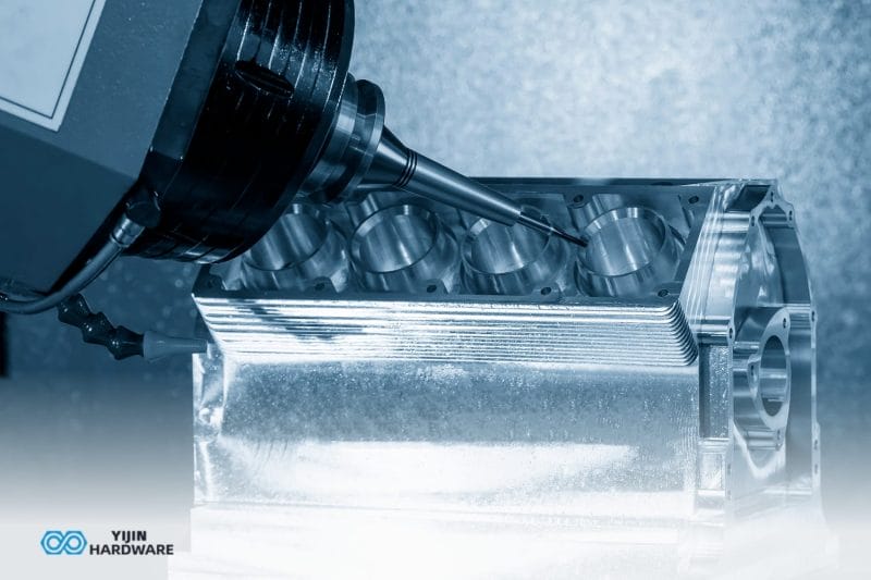
CNC machined shafts are cylindrical components manufactured with accurate measurements to transfer power, torque, and motion in mechanical assemblies. Modern manufacturers like our team at Yijin Solution use modern CNC procedures such as turning & milling to make these shafts.
These precision components serve as the foundation for countless mechanical systems. From automotive drivetrains to aerospace equipment, machined shafts ensure reliable power transmission while maintaining the tight tolerances necessary for optimal performance. The global CNC machining market, which includes shaft production, was valued at USD 67.5 billion in 2023 and is projected to grow at a CAGR of 3.5% from 2024 to 2030 according to Markets and Markets.
Research demonstrates the critical importance of precision in shaft manufacturing: misalignment in rotating shafts contributes to over 50% of bearing failures in industrial machinery, according to Dynamox.
What are the CNC Machining Techniques for Shafts?
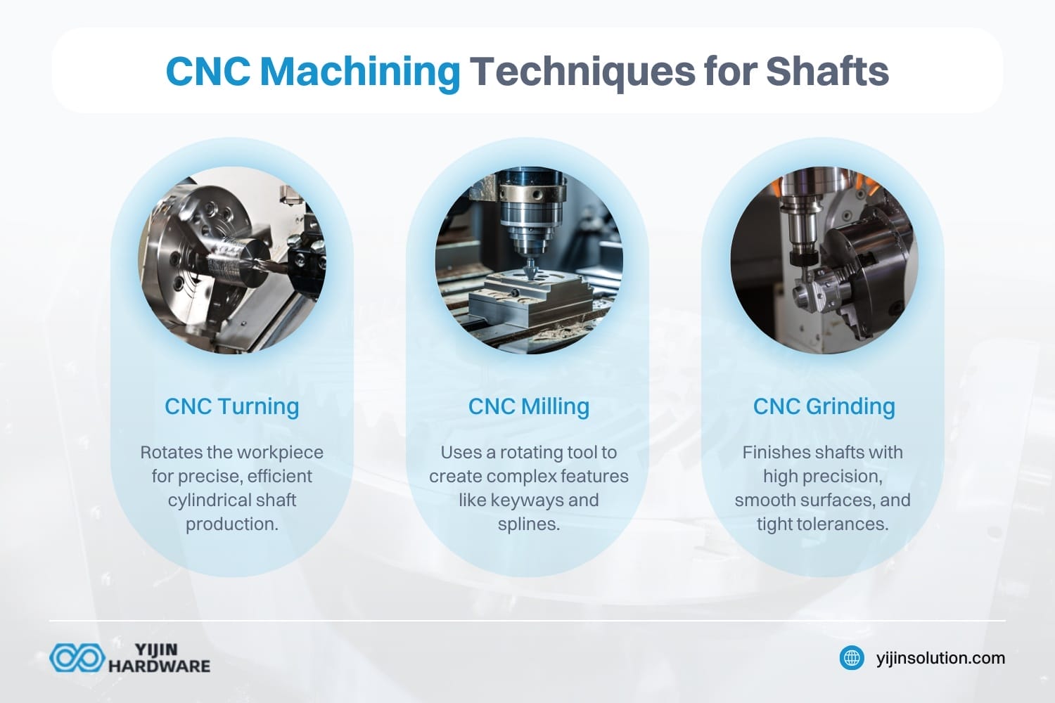
CNC machining techniques are essential for producing high-precision shafts. These techniques include CNC turning, milling, and grinding, each serving specific purposes in shaft manufacturing.
CNC Turning
CNC turning is a primary method for creating cylindrical shafts. It involves rotating the workpiece while a stationary cutting tool shapes it, offering high precision and efficiency in manufacturing symmetrical components. This technique is ideal for producing solid shafts and parts like lead screws. CNC turning is often performed on a lathe, which provides the rigidity needed for precise machining. According to Grand View Research, in 2023, the global market for CNC machining and turning centers reached a value of USD 25.99 billion. It is expected to grow at an annual rate of 6.6% from 2024 to 2030.
CNC Milling
CNC milling is used to create complex features such as keyways, splines, or grooves on the shaft. It involves a rotating cutting tool that removes material from a stationary workpiece, allowing for intricate designs and precision-machined shafts. CNC milling is particularly useful for creating custom machined shafts with specific features like splined shafts.
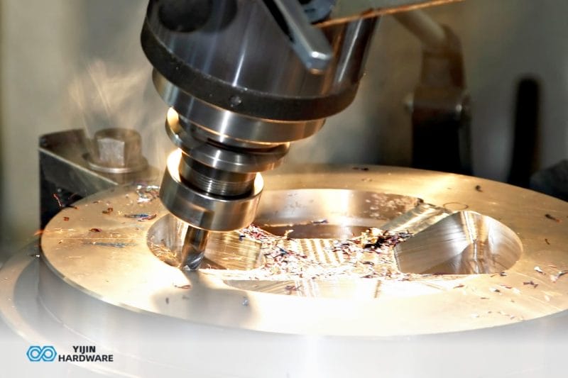
CNC Grinding
CNC grinding is a finishing process used to achieve precise surface finishes and dimensions. It involves using abrasive materials to remove small amounts of material from the surface of the shaft, ensuring smooth operation and reducing wear. Grinding is crucial for achieving the desired surface roughness and tolerance in machined shafts.
What Design Considerations are Important for CNC Machined Shafts?
Designing effective CNC machined shafts requires careful attention to several critical factors including material selection, surface finish requirements, dimensional accuracy, geometric features, and tolerance specifications. Familiarizing yourself with each type of design consideration is crucial for machining the correct shaft for your project.
How do you Select the Right Material?
You must pick a material that meets the particular operational requirements of your shaft. Commonly used materials are steel alloys for strength, stainless steel for corrosion protection and aluminum for light weight. The first step in shaft design is picking suitable material.
Your material choice directly impacts the shaft’s performance, longevity, and suitability for specific applications. For instance, aerospace applications might prioritize titanium’s exceptional strength-to-weight ratio, while food processing equipment would benefit from stainless steel’s corrosion resistance.
Why is Surface Finish Critical?
Surface finishes are critical for reducing wear, friction, and fatigue stress concentrations heavily. Surface finish requirements vary based on the shaft’s function and operating environment:
- For fitting journals, the roughness should be between 0.4 μm‐3.2 μm.
- For bearing journals, the surface roughness is generally between 0.2 μm & 1.6 μm.
These precise specifications ensure optimal performance and longevity. The correct surface finish minimizes friction, reduces wear, and prevents premature failure in high-stress applications.
How Important is Dimensional Accuracy?
Guaranteeing dimensional accuracy is very important for proper system functionality as well as assembly. Bearing journals usually need tight tolerances of IT5‐IT7 to attain accurate positioning. Fitting journals designed for pulleys or gears typically have a little bit of loose tolerances between IT6 & IT9.
If dimensional accuracy is insufficient then increased part wear, misalignment and decreased system performance may happen. Dimensional precision directly impacts the shaft’s compatibility with other components and its overall performance.
High-precision manufacturers can achieve pitch diameter accuracy within ±0.005 mm for transmission shafts, ensuring smooth operation in demanding applications.
What Geometric Features Matter?
Proper geometric properties - including coaxiality, roundness & cylindricity - are very important for uniform load distribution and balanced rotation. If your application requires extra features such as keys or splines, you must add these elements into the shaft design from the beginning.
These geometric considerations ensure shafts rotate without vibration or instability. During rough turning operations, shaft deformation magnitude is typically 2.2 to 2.5 times greater compared to finish turning, making geometric precision critical during final machining stages.
Why are Tolerance Requirements Critical?
A clear definition of tolerance specifications is very important to guarantee compatibility between CNC shaft and the components it connects to - such as bearings or gears. For instance, interference fits demand tighter tolerances as compared to clearance fits to stop parts from slipping during operation. Incorrectly specified tolerances can negatively impact mechanical safety & safety performance.
Tolerances directly influence how effectively the shaft integrates within mechanical systems. Properly specified tolerances prevent issues like slippage, excess friction, or premature failure.
Machining Processes and Techniques
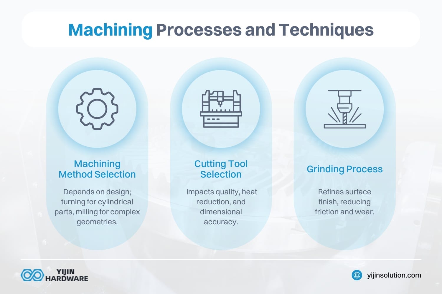
Machining processes for shafts involve various techniques to achieve specific features and surface finishes, from method selection to the grinding process.
Machining Method Selection
The choice of machining method depends on the shaft’s intended application and design specifications. For example, CNC turning is used for cylindrical parts, while CNC milling is preferred for complex geometries like splined shafts. The process involves using a CNC machine for shaft machining, which provides high precision and flexibility.
Cutting Tool Selection
The cutting tool used affects the quality of the machined shaft. Proper tool selection reduces cutting heat and improves dimensional accuracy, ensuring that the shaft meets precise specifications. The cutting tool must be compatible with the workpiece material to avoid damage and ensure smooth operation.
Grinding Process
The grinding process is used to refine the surface finish of the shaft. It involves using a grinding wheel to remove small amounts of material, resulting in a smooth surface that reduces friction and wear. Grinding is essential for achieving the desired surface finish and tolerance in precision machined shafts.
What Additional Techniques Might be used for Specialized Shafts?
Other advanced manufacturing techniques can further enhance shaft production:
- Wire EDM (Electrical Discharge Machining): Creates extremely precise internal features including complex keys, splines, or non-traditional geometries difficult to achieve with conventional cutting tools
- Thread Rolling: Forms threads through deformation rather than cutting, producing stronger threads with better surface finish
- Spline Cutting: Creates specialized spline profiles for power transmission applications
- Induction Hardening: Selectively hardens shaft surfaces to enhance strength, load capacity, and durability
What Types of CNC Machined Shafts Exist?
CNC machined shafts come in various configurations, each designed for specific applications and performance requirements, including solid shafts, hollow shafts, threaded shafts, keyed shafts, and more.
| Shaft Type | Description | Key Features | Manufacturing Considerations |
|---|---|---|---|
| Solid Shafts | Uniform diameter cylindrical components |
| Manufactured primarily through CNC turning and material selection critical for load requirements |
| Hollow Shafts | Cylindrical components with central void |
| Requires precise boring operations, with wall thickness uniformity is critical since they are more complex to manufacture than solid shafts |
| Threaded Shafts | Shafts with internal or external threads |
| Requires thread cutting or rolling, as thread precision affects functional performance. The surface finish also impacts thread efficiency |
| Keyed Shafts | Shafts with keyway cut to secure components |
| Requires milling operations for keyway and key dimension accuracy critical. There may be potential stress concentration at keyway |
| Splined Shafts | Shafts with longitudinal grooves cut along length |
| Requires specialized milling or broaching, with complex geometry that demands high precision |
| Tapered Shafts | Shafts with gradual diameter reduction |
| Requires precision turning for consistent taper. Taper angle precision affects component fit, while surface finish impacts mounting security |
| Stepped Shafts | Shafts with multiple sections of different diameters |
| Requires maintaining concentricity between steps, as the transition radius design affects stress distribution. Multiple diameter changes increase manufacturing complexity |
What are Solid Shafts Used For?
Solid shafts provide maximum strength and rigidity, making them ideal for applications with high torque requirements. These uniform-diameter shafts excel in power transmission applications where deflection must be minimized, such as industrial machinery and automotive drive systems.
How do Hollow Shafts Reduce Weight While Maintaining Strength?
Hollow shafts often bear a central hole or void, allowing fluid, wire, and other components to pass. They usually have low weight, in contrast to solid shafts of similar size. Hollow shafts are applicable in racing vehicles and aircraft to reduce weight. In addition, they are also applicable to conveyor systems, pumps, and medical devices.
The hollow design significantly reduces weight while maintaining much of the torsional strength of solid shafts. This weight reduction is particularly valuable in aerospace and high-performance automotive applications, where every gram matters.
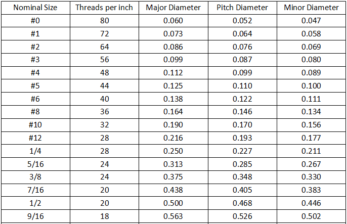
When are Threaded Shafts Necessary?
These machined shafts have internal or external threads cut into them, which match the threads on a corresponding part like a nut. This form of connection is often found in applications requiring frequent attachment or detachment, like electrical or plumbing work. Threaded shafts are also used in threaded spindles, lead screws, and fastening mechanisms.
Threaded shafts convert rotational motion into linear movement, making them essential in positioning systems, adjustable mechanisms, and fastening applications.
How do Keyed Shafts Prevent Slippage?
A keyed shaft is a type of machined shaft with a keyway cut into it to secure components such as sprockets, pulleys, or gears. The machined keyways have the same width as a key. As such, the keyway accommodates the key, engaging the other component’s corresponding teeth to prevent it from rotating independently or slipping. Keyed shafts are ideal for maintaining a connection in high-torque applications like motors and pumps.
The key system creates a mechanical interlock that prevents relative movement between the shaft and connected components. This design is crucial for applications where power transmission must be absolutely secure.
What Makes Splined Shafts Different?
These splined machined shafts have longitudinal grooves or splines cut into them along their length that fit into matching splines machined into a corresponding component, like a pulley or gear. This is a strong form of connection, allowing seamless power transmission since no relative movement occurs between the two parts. They are often utilized in applications requiring precise positioning or torque transmission, like automotive transmission or gear couplings.
Splined shafts can be categorized as having either involute or straight splines, depending on the application requirements:
- Involute splines provide better load distribution and smoother engagement in rotary applications
- Straight splines are simpler and used when precise torque transmission isn’t critical
When are Tapered Shafts Preferred?
A tapered shaft has a gradual reduction in diameter along its length. Tapered shafts are often used in applications where components like automotive wheel hubs, pulleys, or gears must be securely mounted.
The tapered design creates a self-centering effect and facilitates component mounting and removal. As the shaft is inserted or tightened, the taper creates a secure fit that centralizes the component automatically.
What are Stepped Shafts?
Stepped shafts feature multiple sections with different diameters along their length. This design accommodates different components requiring varying shaft sizes or enables proper positioning of elements like bearings, gears, and pulleys along the shaft length.
Applications of CNC-Machined Shafts
CNC-machined shafts are used in a variety of applications across different industries, including aerospace and automotive.
Industrial Applications
Shafts are essential in industrial machinery, serving as power transmission elements in food processing, textile manufacturing, and other sectors. They must operate at high speeds and withstand high-torque conditions. Custom-machined shafts are often required to meet specific application needs, such as reducing weight while maintaining strength.
Aerospace and Automotive
In aerospace and automotive industries, precision-machined shafts are critical for ensuring reliability and performance. These shafts often require custom designs and materials to meet specific application needs. For instance, splined shafts are used in applications where torque transmission is critical.
Yijin Solution specializes in machining precision shafts with high dimensional accuracy and surface finish. Our custom CNC machining services cater to diverse application needs, providing tailored solutions for industries requiring high-quality shaft components. Contact us today to explore how our expertise can meet your specific requirements.
CNC Shaft Machining Factory FAQs
As for the splines, are they involute, or just straight?
Splines can be either involute or straight, depending on CNC precision machining shaft requirements. Involute splines provide better load distribution and smoother engagement in rotary applications. Straight splines are simpler and used in cases where precise torque transmission isn’t critical. Choosing the right spline type depends on shaft applications and overall performance needs.
But why should you care about custom shaft machining?
Custom shaft machining ensures precision, durability, and efficiency for specialized shaft parts in various industries. Standard shafts may not meet complex shaft features required for advanced machine tool systems. A CNC machine shop can produce high-accuracy shafts tailored to unique performance demands. Custom machining also enhances compatibility with other components, reducing assembly issues.
What are the advantages of turning and milling combined machining?
Turning and milling combined machining improves efficiency by integrating multiple techniques used in CNC shaft production. A turning tool shapes the cylindrical features, while milling refines complex shaft features in one setup. This hybrid approach minimizes repositioning, reducing errors and improving machining precision. Combining these processes enhances productivity, making it ideal for high-precision spindle and shaft applications.
Back to Top: What is a CNC Machining Shaft?