


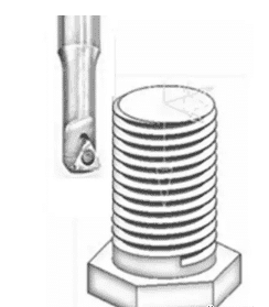
The Working Principle
Using the G03/G02 three-axis linkage spiral line, the tool along the surface of the workpiece (hole wall or cylindrical appearance) cutting. After one week of spiral interpolation, tool Z goes one pitch in the negative direction.
Programming principle: G02 Z-2.5 I3.
Z-2.5 equals a pitch of 2.5mm
Suppose the radius of the tool is 5mm, then process the right-hand screw thread of M16.
Advantage
The use of a three-axis CNC milling machine or machining center for thread processing, compared with traditional thread processing.
1. Such as the pitch of the 2-thread milling cutter can process a variety of nominal diameters, the pitch of 2mm internal and external threads.
2. Using milling mode processing thread, thread quality than the traditional way processing quality is higher.
3. It’s used as a machine clip blade tool, for a long lifetime.
4. Multi-tooth thread milling cutter processing, processing speed is far more than tapping.
5. After the first check, the processing quality of the parts behind is stable.
Method of Use
G65 P1999 X_ Y_ Z_ R_ A_ B_ C_ S_ F_
The center position of XY threaded hole or MALE thread X=#24 Y=#25
Z thread machining to the bottom, Z-axis position (absolute coordinates) Z=#26
R Quick position (safe height) start cutting the thread at position R=#18
A thread pitch A=#1
B thread nominal diameter B=#2
C Thread milling cutter tool radius C=#3 is negative for internal thread and positive for external thread processing
S spindle speed
F Feed speed is mainly used to control the cutting tool per tooth
G65 P1999 X30 Y30 Z-10 R2 A2 B16 C-5 S2000 F150;
M16 right-handed thread with pitch 2 and depth 10 was machined at the position of X30Y30. The spindle speed was 2000 and the feed progress was 150mm/min
Macroprogram Code
O1999;
G90G94G17G40;
G0X #24 Y #25; Quickly locate the X and Y coordinates in the center of the thread
M3S #19; The spindle is turning forward at the set speed
#31 = #2 * 0.5 + #3; Calculate the tool offset
18 – #32 = 1; The position of the first cut when the cutter goes the spiral line
#33 = #24 to 31; Calculate the position where the tool moves to the starting point of the thread
G0Z#18; The tool is quickly positioned to point to R
G1X #33 F #9; The tool is interpolated straight to the starting point of the helix, which is in the negative direction of X
N20 G02Z-#32 I#31; Take the offset as the radius, take the pitch as the helical Z down cutter (absolute coordinate)
IF [#32 le #26] GOTO30; Jump is performed when the current Z position is greater than or equal to the set Z position to the bottom
#32 = #32 – #1; Next helix depth target position in Z direction (absolute coordinates)
GOTO20;
N30;
IF [#3 gt0] THEN #6 = #33 – #1; For external thread, the tool is retracted by one pitch in the negative X direction
IF [#3 lt0] THEN #6 = #24; For internal threads, the tool moves to the center of the thread when the tool is retracted
G0X#6
G90 G0Z#18; Lift knife to a safe height
M99.