Call Us Today! (+86) 188-2253-7569
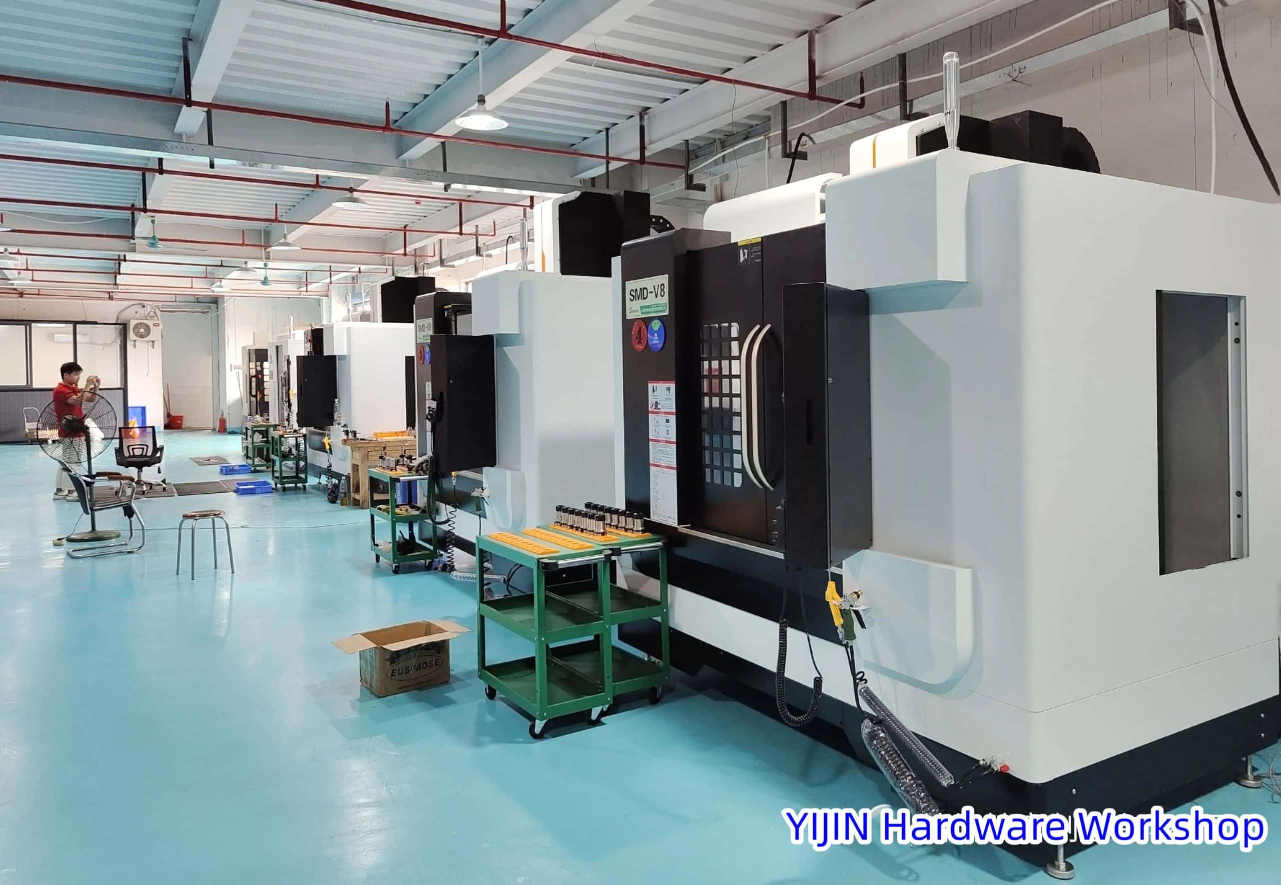
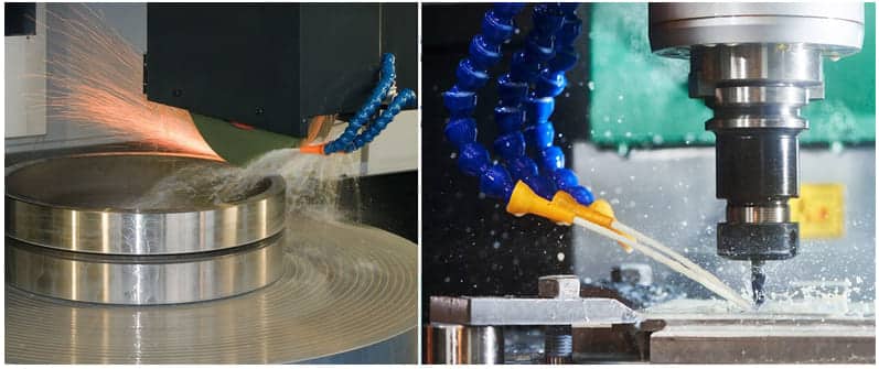
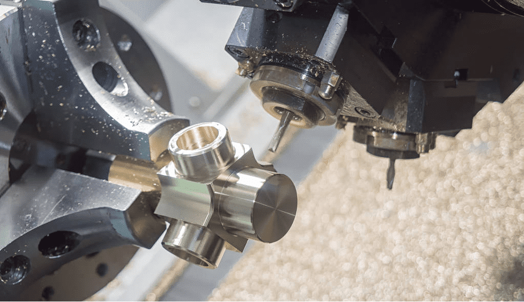
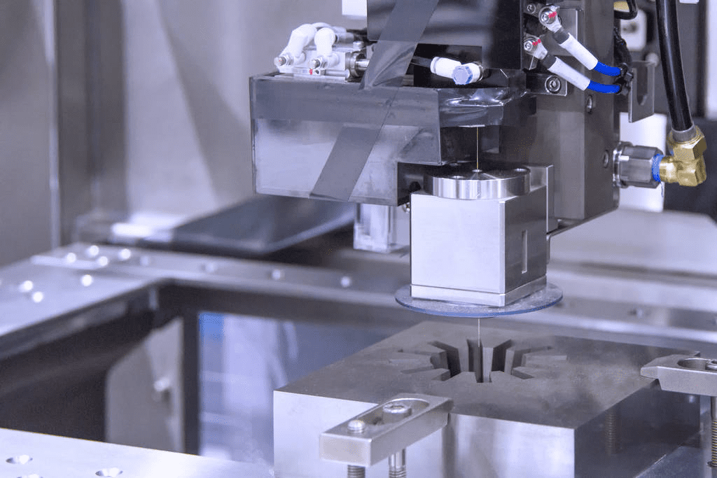
CNC machining is one of the most popular machining processes now. There are many problems in CNC machining. Today we will talk about 10 common CNC machining problems and how to improve them.
1. Workpiece Overcut
Causes
- Spring knife, tool strength too long or too small, resulting in tool spring knife.
- Improper operation by the operator.
- Uneven cutting allowance (eg: 0.5 on the side of the curved surface and 0.15 on the bottom)
- Improper cutting parameters (eg: tolerance too large, SF setting too fast, etc.)
Improvement Methods
- Rule of knife use: use big ones, not small ones, use short ones, not long ones.
- Add the corner cleaning program, and the margin should be kept uniform (the side and bottom margins should be the same).
- Reasonably adjust the cutting parameters, and round the corners with a large allowance.
- Using the machine SF function, the operator fine-tunes the speed to achieve the best cutting results.
2. Midpoint Problem
Cause
- The operator’s manual operation is not accurate.
- There are burrs around the mold.
- The centering rod is magnetic.
- The sides of the mold are not vertical.
Improvement Methods
- The manual operation should be carefully checked repeatedly, and the points should be at the same point and the same height as much as possible.
- Deburr the edges of the mold with an oilstone or file. Clean the edges with a rag and confirm by hand.
- Demagnetize the centering rods before centering the mold (use ceramic centering bars or others).
- Check whether the four sides of the mold are vertical (if the verticality error is large, you need to review the plan with the fitter).
3. Tool setting problem
Cause
- Inaccurate when done manually by the operator.
- The tool is set up incorrectly.
- The blade on the flying knife is wrong (the flying knife has a certain error).
- There is an error between the R knife and the flat bottom knife and the flying knife.
Improvement Methods
- The manual operation should be carefully checked repeatedly, and the knife should be set at the same point as much as possible.
- When the tool is clamped, blow it clean with an air gun or wipe it with a rag.
- One blade can be used when the blade on the flying knife needs to measure the shank and smooth bottom surface.
- A separate tool setting program can avoid the error between the R tool, the flat tool, and the flying tool.
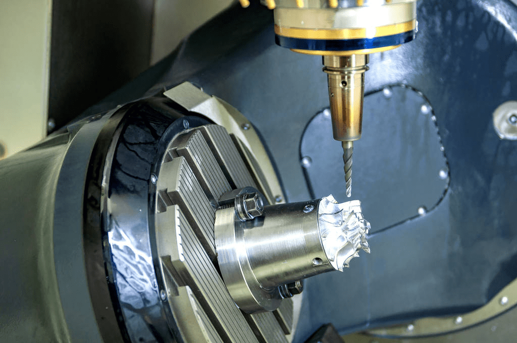
4. Collider – Programming
Cause
- The safety height is not enough or not set (the tool or chuck hits the workpiece during rapid traverse G00).
- The tool on the program sheet and the actual program tool are wrongly written.
- The tool length (edge length) and the actual machining depth on the program sheet are wrong.
- The depth Z-axis fetching and the actual Z-axis fetching on the program sheet are wrongly written.
- The coordinates are set incorrectly during programming.
Improve Methods
- Accurate measurement of the height of the workpiece also ensures that the safety height is above the workpiece.
- The tool on the program list should be consistent with the actual program tool (try to use the automatic program list or use the picture to output the program list).
- Measure the depth processed on the workpiece, and write the length of the tool and the length of the blade clearly on the program sheet (generally, the length of the tool holder is 2-3MM higher than the workpiece, and the length of the blade is 0.5-1.0MM).
- Take the actual Z-axis number on the workpiece and write it clearly on the program sheet. (This operation is generally written for manual operation and needs to be checked repeatedly).
5. Collider-Operator
Cause
- Depth Z-axis tool setting error.
- The number of touches and operands is wrong in the score (such as unilateral fetching without tool feed radius, etc.).
- Use the wrong tool (for example D4 tool is processed with the D10 tool).
- The program goes wrong (eg: A7.NC goes to A9.NC).
- The handwheel is turned in the wrong direction during manual operation.
- Press the wrong direction during manual rapid traverse (eg -X press +X).
Improvement Methods
- The depth Z-axis tool setting must pay attention to the position of the toolset. (bottom, top, analysis, etc.).
- The number of hits in the score and the operand should be checked repeatedly after the completion of the operation.
- When clamping the tool, it should be repeatedly checked with the program sheet and the program before installation.
- The program should go one by one in order.
- When using manual operation, the operator himself has to strengthen the operating proficiency of the machine tool.
- In manual rapid movement, the Z-axis can be raised to the workpiece before moving.
6. CNC Machining Common Problems: Surface Accuracy
Cause
- The cutting parameters are unreasonable, and the surface of the workpiece surface is rough.
- The knife edge is not sharp.
- The tool clamping is too long, and the blade avoidance is too long.
- Chip removal, air blowing, and oil flushing are not good.
- Program the tool pass method (consider down milling as much as possible).
- The workpiece has burrs.
Improvement Methods
- Cutting parameters, tolerances, allowances, speed, and feed settings should be reasonable.
- Tool operators are required to check and replace tools irregularly.
- When clamping the tool, the operator should try to clip it short, and the blade should not be too long.
- For the lower cutting of flat knife, R knife, and round nose knife, the speed and feed set should be reasonable.
- The workpiece has burrs: it is directly related to our machine tool, cutting tool, and cutting method. Therefore, we need to understand the performance of the machine tool and make up for the edge with burrs.
7. Flaking
Cause and Improvement Methods
- Feeding too fast: Slow down to a suitable feed rate.
- Feed too fast at the start of cutting: Decrease the feed rate at the start of cutting.
- Clamping loose (tool): Clamp.
- Clamping loose (workpiece): Clamp.
- Insufficient rigidity (tool): Use the shortest knife allowed, the shank is a little deeper, and try down milling.
- The cutting edge of the tool is too sharp: Change the fragile cutting edge Angle, to one edge.
- Insufficient machine and tool holder rigidity: Use a rigid machine tool and tool holder.
8. Wear
Cause and Improve Methods:
- Machine speed is too fast: Slow down, and add enough coolant.
- Hardening of the material: Use advanced cutting tools and tool materials to increase surface treatment.
- Chip adhesion: Change the feed speed, and chip size or clean the chips with cooling oil or an air gun.
- Improper feed rate (too low): Increase the feed rate and try down milling.
- Inappropriate cutting angle: Change to the appropriate cutting angle.
- The primary clearance angle of the tool is too small: Change to a larger rear angle.
9. Damage
Cause and Improve Methods:
- Feeding too fast: Slow down the feed rate.
- Too much cutting: With a smaller cutting amount per edge.
- Blade length and overall length are too large: The shank clamp is deeper, use a short knife, and try down milling.
- Too much wear Regrinding at the beginning.
10. Vibration
Cause and Improve Methods:
- Feed and cutting speed too fast: Corrected feed and cutting speed.
- Insufficient rigidity (machine tool and tool holder): Use a better machine and tool holder or change cutting conditions.
- The rear corner is too large: Change to a smaller relief angle, and process the land (grinding the edge with a whetstone).
- Clamp loose: The clamping workpiece.
Consider Speed and Feed
The relationship between the three factors of speed, feed, and depth of cut is the most important factor in determining the cutting effect. Inappropriate feed and speed often lead to reduced production, poor workpiece quality, and large tool damage.
- The low-speed range for hardness material, Material with high toughness, Materials that are difficult to cut, Heavy cutting, Minimal tool wear, and Maximum tool life.
- The high-speed range for Soft material, Good surface quality, Smaller tool od, Light cutting, Brittle workpiece, Manual operation, Maximum processing efficiency, and Nonmetallic material.
- Use high feed for Heavy and rough cutting, Rigid structure, Workable material, Roughing tool, plane cutting, Low tensile strength material, Rough milling cutter
- Use low feed for Light machining, fine cutting, Brittle structure, Difficult-to-machine materials, Small tools, Deep groove machining, High tensile strength material, and a Finishing tool.