


A design reaches the stage of physical validation, and the prototyping route chosen in that first week is hard to change once parts are on order. That route decides the tolerance the parts will hold, the date they arrive on the bench, and what each design revision costs to test in time and money.
Aluminum rapid prototyping is the quick production of functional aluminum parts for validation ahead of production tooling.
A prototype that does not represent the production part sends the design team back a cycle, so the decisions made before the file goes out carry real weight. Most of that weight sits in four decisions, covering alloy, tolerance callouts, surface finish, and quantity, and each one reappears in the quote and the schedule.
Why Aluminum Suits Prototype Parts

Aluminum earns its place in prototyping on two measurable properties: it cuts fast and it weighs little.
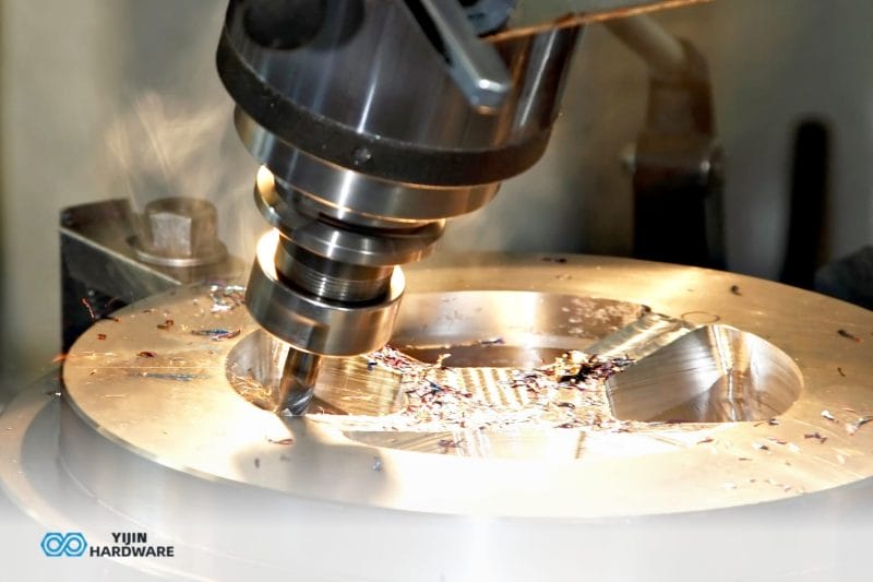
Machinability comes first. Aluminum alloys run at cutting speeds several times those used on carbon steel, and they load the tool far less. Geometry that takes a full shift of spindle time in stainless steel can often come off an aluminum billet in a fraction of that time. Aluminum prototype turnaround is counted in days as a result.
Density comes second. At about 2.7 g/cm³, aluminum sits near one-third the density of steel. When the production part is also aluminum, the prototype gives realistic weight, balance, and vibration behavior during testing.
Consumer electronics, automotive, robotics, and medical device programs all draw on aluminum prototypes for that combination. Within that material family, the alloy is the next decision.
Which alloy fits the prototype’s job?
Four alloys cover most prototype work, named under the designation system published by the Aluminum Association.
The table below gives typical values for each temper as listed in the ASM material data sheets. Specified minimums sit lower and shift with product form and section thickness.
Table 1. Typical mechanical values for common prototype alloys
| Alloy and temper | Zugfestigkeit | Streckgrenze | Relative machinability | Anodizing response | Typical prototype use |
|---|---|---|---|---|---|
| 6061-T6 | 310 MPa | 276 MPa | Good, the general reference point | Uniform, predictable color | Structural brackets, housings, fit validation |
| 7075-T6 | 572 MPa | 503 MPa | Good to very good, chips break cleanly | Duller and less even from the zinc content | Parts that must survive the production load case |
| 5052-H32 | 228 MPa | 193 MPa | Fair, tends to smear | Excellent, clear, and even | Formed panels, corrosion exposure |
| 6063-T6 | 241 MPa | 214 MPa | Fair, cuts gummy | Excellent, bright, and even | Extruded profiles, cosmetic frames |
6061 covers structural and fit validation. 7075 applies when the prototype has to survive the load case the production part will see, and when the higher material cost buys that confidence.
What the Machining Sequence Involves
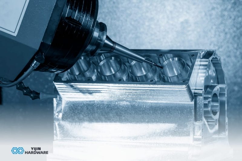
The sequence starts with a solid billet and a CAM program written against the model. The programmer decides how the part is held, how many orientations are needed to reach every feature, and which tools can enter the smallest internal corners. Each new orientation is a setup, and each setup carries its own fixture, program, and zero point.
Setup count is the lever. A part needing four setups costs and takes materially more than the same geometry reoriented to need two. Five-axis machining matters here less for the axis count than for what it removes. Features that a three-axis machine reaches across four setups may come off a five-axis machine in one.
Consolidating features onto fewer faces during design does more for a prototype schedule than a request for expedited handling. Setup count is one of the first things a supplier reviews when quoting aluminum prototype machining services.
What actually drives the lead time?
Quoted turnaround for an aluminum prototype commonly lands at 5 to 10 working days. However, that figure says nothing about which part of the process holds the schedule.
The table below breaks elapsed time into its main components. The shares are indicative for a moderately complex machined part and shift with geometry, quantity, and shop loading.
Table 2. How prototype lead time splits
| Lead time driver | Indicative share of elapsed time | What a design decision can do about it |
|---|---|---|
| CAM-Programmierung | 10 to 15% | Simpler feature geometry and standard hole sizes shorten programming |
| Fixture preparation | 10 bis 20 % | A flat datum face and clampable stock avoid custom soft jaws |
| Setup changes | 15 bis 25 % | Consolidating features onto fewer faces removes whole setups |
| Machining cycle | 20 to 30% | Larger internal radii admit larger tools and faster passes |
| Surface finishing queue | 15 to 30% | Finishing is batched offline, so a late cosmetic callout adds days |
| Dimensional inspection | 5 to 15% | Fewer critical callouts shorten first-article measurement |
Finishing and inspection sit outside the machining cycle entirely. A cosmetic requirement added after the model is released commonly moves the delivery date further than a geometry change does.
What Tolerances are Achievable on an Aluminum Prototype?

Unless a drawing states otherwise, general tolerances on a machined prototype follow ISO 2768. The medium class permits +/-0.1 mm on dimensions from 0.5 to 3 mm, +/-0.2 mm from 6 to 30 mm, and +/-0.3 mm from 30 to 120 mm. The fine class halves those bands.
A drawing marked ISO 2768-m therefore already carries a tolerance on every dimension left untoleranced. Features needing tighter control are called out individually, and any individually toleranced dimension overrides the general class.
Tighter tolerances are bought per feature, not applied across a part. A blanket tight callout adds machining and inspection time to dimensions that play no part in the validation, without improving what the prototype proves. The Leitfaden zu Toleranzen bei der CNC-Bearbeitung sets out that logic in more detail.
Tolerance by feature type
Achievable tolerance varies by what is being held. The values below are typical for machined aluminum and depend on part geometry, alloy, section stiffness, and setup count. They are indicative rather than guaranteed, so any figure a design depends on is confirmed against the actual model before release.
Table 3. Typical achievable tolerance by feature type
| Feature type | Typical achievable range | What moves it | When to call it out |
|---|---|---|---|
| Lineare Abmessungen | +/-0.05 to 0.10 mm | Setup count and thermal growth during the cycle | Mating dimensions and hole spacing |
| Bore diameters | +/-0.01 to 0.03 mm when reamed or bored | Tool condition and whether the bore is drilled, reamed, or bored | Bearing seats and press fits |
| Flatness across a face | 0.05 to 0.15 mm over 100 mm | Residual stress in the billet and clamping distortion | Sealing faces and optical mounts |
| Thin-wall sections | +/-0.10 mm, widening as wall thickness falls | Deflection under cutting load | Any wall below roughly 1 mm |
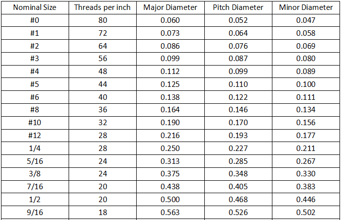
| Merkmale mit Gewinde | Class fit per the thread standard | Tapping method and whether the hole is anodized afterward | Threads taking a fastener under load |
Flatness and thin-wall values move the most between suppliers, because both follow from fixturing practice rather than machine capability. When a drawing cites a geometric class such as ISO 2768-mK, untoleranced flatness, perpendicularity, and run-out fall under ISO 2768-2.
Design Decisions That Change the Cost and the Part
Four design decisions set most of a prototype’s cost. Some change the price, some change what the prototype can prove, and anodizing changes both.
Tolerance and finish callouts
Surface finish follows the same per-feature logic as tolerance. A callout of Ra 1.6 µm across every surface buys a finishing pass everywhere, though the validation question usually concerns one sealing face. Holding the fine finish to that face and leaving the rest as-machined removes a large share of the finishing time.
Wall thickness and internal radii
Thin walls deflect under cutting load, which forces lighter passes and a longer cycle. Below roughly 1 mm in aluminum, wall thickness starts to drive the machining strategy rather than follow it, so the achievable minimum is confirmed per part.
Internal corner radius sets the smallest tool that can reach the corner, and small tools cut slowly. Opening a radius from 1 mm to 3 mm can remove hours from a cycle.
What anodizing does to a fit-check prototype
Anodizing converts the surface, and the oxide layer grows into the aluminum and outward from it in roughly equal proportion. Type II coatings typically fall between 5 and 25 µm total, and Type III hardcoat runs from about 25 to 100 µm.
On a diameter, the outward growth counts twice, because both sides grow. A bore given a 25 µm coating closes by roughly 0.025 mm across its diameter, and a shaft of the same nominal size grows by the same amount.
On a fit-check prototype, fit-critical features are either masked before anodizing or toleranced on the drawing as before-coating or after-coating dimensions. Growth varies with alloy, coating type, and processor, so the figure is confirmed with the finisher. Anodizing applies to machined, formed, and cast aluminum parts on the same terms.
Quantity and the setup cost split
On a single prototype, programming and fixture preparation dominate unit cost, because both are paid once regardless of quantity. Spread across a small batch, that setup changes the arithmetic, so an order of five often costs little more in total than an order of one.
When the Prototype Should Be Cast Instead
A machined prototype settles dimensional accuracy, fit, assembly clearance, and whether the design can be held to the tolerances the drawing asks for. It does this in days, without tooling, and it can be revised by editing a program and cutting another billet.
Casting behavior is a separate question. Wall fill, shrinkage across a section change, draft angle adequacy, and porosity distribution all come from molten metal entering a mold. A part machined from 6061 billet does not share the grain structure or density behavior of an A380 die casting. It stands in for the shape without standing in for the material condition.
Rapid prototype aluminum castings need a mold or tooling before the first part exists, which adds weeks to the schedule. Many programs settle on the same sequence, with machined parts first while the geometry is still moving and cast parts once the shape is stable.
The same logic applies to other materials, as set out in CNC prototype machining across materials.
What Carries Forward Into Production
The prototyping exercise produces more than parts; it produces a set of decisions that either carry into production or get made a second time.
Four things carry forward: the alloy and temper, the dimensions identified as critical, the finish specification, and the inspection points chosen for first-article measurement. Locking these at the prototype stage removes them from production negotiation.
Three things change. Fixturing that was a one-off cost becomes an amortized one, so purpose-built workholding turns into a sensible investment. Cycle time optimization that made no sense across five parts pays back across 5,000, and inspection moves from measuring every part to a sampling plan tied to the critical dimensions.
Yijin Solution machines custom aluminum parts across both stages in the same Shenzhen facility and under the same quality system, which keeps drawing interpretation consistent as volumes rise.
The prototyping route is decided by what the part has to prove, since dimensional accuracy and fit are machining questions, while casting behavior is a casting question. Yijin Solution machines custom aluminum prototypes from 6061 and 7075 billet, with a free DFM review included at the quote stage.
With every part machined in the same Shenzhen facility and under the same quality system, drawing interpretation remains consistent as volumes rise. Engineers can upload their drawings and receive a quote and lead time estimate for their aluminium prototype.
Aluminum Rapid Prototyping FAQs
What files are needed to quote an aluminum prototype?
An aluminum prototype quote needs a 3D model in STEP or IGES format, which carries the geometry the CAM programmer works from. Native CAD files are usually accepted as well. A 2D drawing is added whenever tolerances, surface finish, threads, or material condition differ from the defaults, because none of that lives inside the solid model.
Can an aluminum prototype be machined without a 2D drawing?
Machining from a model alone is common for early geometry checks. Without a drawing, the supplier applies general tolerances and a standard as-machined finish and interprets threads from the modeled feature. Any feature carrying a fit, a surface finish requirement, or a specific thread class needs a drawing to be quoted and inspected against.
How many prototype iterations are typical before design freeze?
Two to three iterations is a common pattern for a moderately complex aluminum part, though the count depends on how many open questions the first round is built to answer. Rounds shorten when each iteration tests a defined list and when DFM feedback is applied before the next order rather than after it.
Does a machined aluminum prototype come with material certification?
Material certification at the prototype stage is usually supplied on request rather than by default. A mill certificate traces the billet to its heat number and confirms alloy and temper. The request is worth making when prototype test data will support a production decision or when the part enters a regulated development file.
Zurück zum Anfang: Aluminum Rapid Prototyping: Tolerances, Lead Times, and Process Selection






 English
  Spanish
  German
  French