
Understanding the individual parts of a CNC machine is essential for engineers specifying equipment, maintenance teams troubleshooting issues, and manufacturers evaluating machine capabilities for custom CNC projects.
This guide breaks down CNC machine components into their functional categories, explains how each system contributes to machining performance, and provides technical specifications relevant to part quality, surface finish, and production efficiency. Whether you’re evaluating a machine shop’s capabilities, selecting CNC machining services for prototype development, or designing parts with complex geometries for high-volume production, understanding these core systems will help you make informed decisions.
Key Takeaways
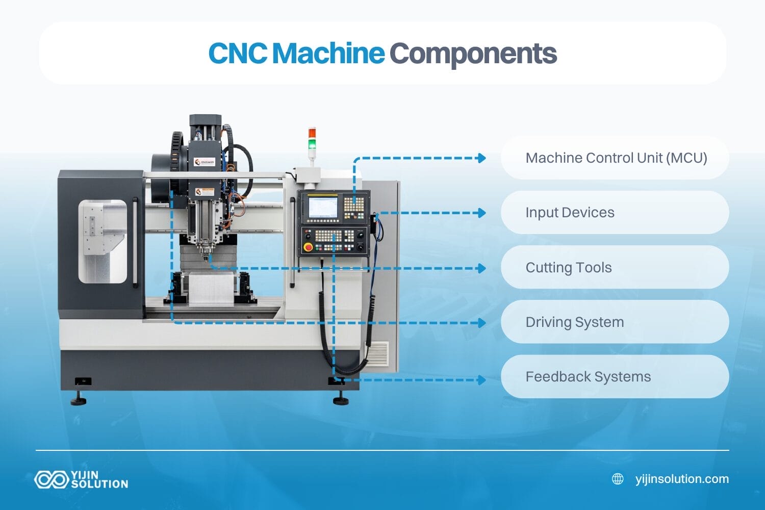
- CNC machine components are divided into five primary systems: control, motion/drive, spindle/tooling, structural, and auxiliary
- The Machine Control Unit (MCU) interprets G-code from CAD files and coordinates multi-axis motion, tool changes, and process parameters to maintain tight tolerances (±0.0005″ or better)
- Drive systems using ball screws and linear guides determine positioning accuracy and repeatability, critical for parts requiring precision threading, external threads, or geometric tolerances
- Spindle rigidity and cutting tool selection directly affect surface finish, machinability across metals and plastics, and the ability to machine hardness ranges from soft aluminum alloys to hardened steel
- Understanding CNC machinery parts enables better communication with machine shops, faster quotes, optimized part designs for manufacturing, and realistic expectations for lead times and turnaround time
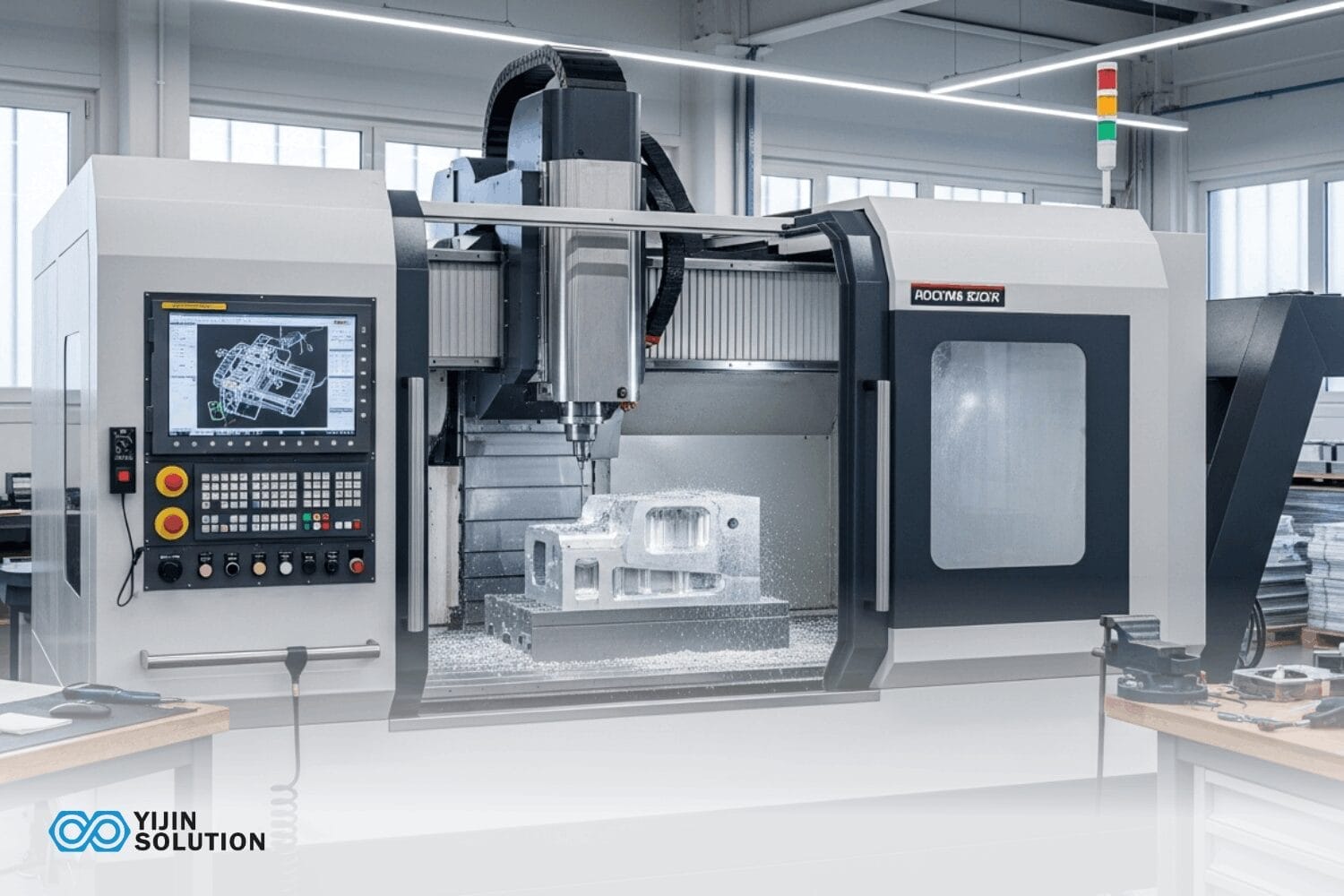
The Five Core Systems of CNC Machinery Parts
Every CNC machine, whether it’s a mill, lathe, or 5-axis machining center, is built from five integrated systems. Each system affects specific aspects of part quality, production efficiency, and the range of materials and geometries the machine can handle.
1. Control System Components
The control system is the “brain” of the CNC machine, responsible for interpreting design files and coordinating all machine functions.
Machine Control Unit (MCU)
The MCU processes G-code instructions generated from CAD files or 2D technical drawings and translates them into motion commands for each axis. Modern CNC controllers support:
- Multi-axis interpolation for simultaneous coordinated motion across 3, 4, or 5 axes
- Look-ahead processing to optimize feed rates through complex toolpaths and maintain surface finish quality
- Tool offset management for automatic compensation when tools wear
- Adaptive feed control to prevent tool breakage in variable-depth cuts
Human-Machine Interface (HMI)
The operator panel allows program loading, machine setup, offset entry, and real-time monitoring. Industrial HMIs display spindle load, axis positions, feed rates, and diagnostic codes for troubleshooting.
Input Devices
Programs are loaded via USB drives, Ethernet connections, or RS-232 serial interfaces. Advanced machine shops use DNC (Direct Numerical Control) systems to stream programs directly from CAM workstations, reducing setup time for high-volume production runs.
2. Motion and Drive System Components
The drive system moves your cutting tools. It places them exactly over your material. This precise movement guarantees accurate parts. A good drive system helps your machine hold tight tolerances on every single cut.
Linear Motion Components
| Component | Function | Impact on Part Quality |
|---|---|---|
| Ball Screws | Convert rotary motor motion to linear axis travel with minimal backlash | Positioning accuracy for tight tolerances; thread pitch consistency for external threads |
| Linear Guide Rails | Support moving components (table, saddle, spindle head) with minimal friction | Surface finish quality; prevents vibration-induced chatter marks |
| Servo Motors | Drive each axis with closed-loop position feedback | Repeatability across production runs; dimensional consistency |
| Encoders | Provide position feedback to controller for error correction | Maintains nominal dimensions within specified tolerance bands |
Ball Screw Specifications
Ball screw lead (the distance traveled per revolution) and diameter determine maximum feed rates and positioning resolution. Precision-ground ball screws achieve positioning accuracy of ±0.0001″ per 12″ of travel, essential for parts requiring geometric dimensioning and tolerancing (GD&T).
Servo vs. Stepper Motors
Production CNC machines rely on servo motors. These motors include a smart feedback system. They instantly detect and fix any missed steps. This stops tiny errors from adding up over time. Stepper motors lack this feedback feature. Heavy cutting forces can make them lose their exact position. Steppers work fine for simple prototypes. However, they are risky for high-volume production. You need servos to mass-produce precision parts reliably.
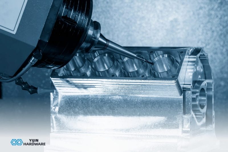
3. Spindle and Tooling System
The spindle holds and rotates cutting tools to remove material from the workpiece. Spindle characteristics determine what materials can be machined, the achievable surface finish, and production efficiency.
Spindle Types and Specifications
Direct-Drive Spindles:
Motor is directly coupled to the spindle shaft. Common in high-speed machining centers running at 12,000–40,000 RPM for aluminum alloys, plastics, and soft metals. Lower torque than belt-driven designs.
Belt-Driven Spindles:
Motor connected via belt transmission. Provides higher torque at lower speeds (1,000–8,000 RPM), suitable for heavy interrupted cuts in carbon steel, stainless steel, and high-hardness materials. Commonly used in mills and lathes for general machining.
Spindle Taper Standards:
Tool holders mount to the spindle via standardized tapers:
- CAT 40/50 (most common in North America for mills)
- BT 40/50 (common in Asian-manufactured equipment)
- HSK (European standard for high-speed machining)
Runout simply means your cutting tool wobbles. A wobble over 0.0005 inches causes major problems. It quickly ruins your smooth surface finish. It also destroys your expensive cutting tools much faster.
Automatic Tool Changers (ATC):
Production machines include ATCs with tool magazines holding 12–40+ cutting tools. Tool change time (1.5–6 seconds) impacts cycle time for parts requiring multiple operations (drilling, milling, threading, chamfering).
Cutting Tools and Tool Holders:
CNC machines use indexable carbide inserts, solid carbide end mills, drills, reamers, taps, and specialized tools. Tool material selection depends on workpiece material:
- Carbide: Standard for aluminum, brass, plastics; wear-resistant for high-volume production
- HSS (High-Speed Steel): Lower cost for prototyping, acceptable for short runs
- Coated Carbide (TiN, TiAlN): Extends tool life 2–5× in stainless steel and alloy steels
- CBN (Cubic Boron Nitride): Required for hardened steels (>45 HRC) and heat-treated parts
4. Structural Components
The machine frame and structural elements provide rigidity to resist cutting forces without deflection, thereby maintaining dimensional accuracy.
Machine Base and Frame
Cast iron is the standard material for machine bases. It easily absorbs heavy cutting vibrations. It also handles heat very well. High-end machines often use polymer concrete or granite blends. These advanced materials stop vibrations even better. They keep their exact shape during room temperature changes. This extreme stability is crucial. It helps your shop hold very tight tolerances on every single part.
Machine Table/Bed
The workpiece mounts to the table, which may be stationary (vertical machining centers) or travel along the Y-axis (horizontal mills). Tables include:
- T-slots: Standardized slots for mounting vises, fixtures, and clamps
- Grid or tapped hole patterns: For modular fixturing systems
- Integrated coolant channels: For through-table flood coolant delivery
Ways and Guideways
They are the tracks for your machine. Moving parts like the saddle, table, and spindle head glide along these smooth surfaces. Box ways use a traditional sliding design. They offer massive stiffness for heavy cutting. Linear roller guides work differently. They create very little friction. This allows your machine parts to move much faster. They simply sacrifice a tiny bit of rigidity compared to heavy box ways.
5. Auxiliary Systems
Supporting systems enable unattended operation, improve surface finish, and extend tool life.
Coolant System
Flood systems wash away metal chips. This steady liquid cools the cutting area and leaves a smooth surface finish. Through-spindle coolant pushes high-pressure fluid directly through the tool. You absolutely need this powerful feature for deep holes and tough titanium.
Chip Removal
Chip conveyors automatically remove metal chips from the work area. Critical for lights-out manufacturing and preventing chip re-cutting, which damages surface finish.
Enclosures and Safety Interlocks
Industrial machines include full enclosures with interlocked doors that stop spindle motion when opened, meeting OSHA and CE safety standards.
CNC Milling Machine Parts vs. CNC Lathe Parts
While sharing common control and drive components, mills and lathes differ in how they orient and move the workpiece relative to the cutting tool.
Parts of CNC Milling Machine
Vertical Machining Center (VMC) Configuration:
- Spindle oriented vertically (Z-axis)
- Table moves in X and Y axes
- Workpiece remains stationary during cutting
- Ideal for flat parts, pockets, slots, and 2D profiles
Horizontal Machining Center (HMC) Configuration:
- Spindle oriented horizontally
- Often includes a rotary table (B-axis) for 4-axis machining
- Better chip evacuation for heavy cuts
- Commonly used for prismatic parts with features on multiple faces
Key Milling Components:
- Quill: ( vertical spindle travel for drilling operations)
- Knee: ( supports the table and provides Z-axis motion on manual mills.)
- Saddle: (supports table, travels on Y-axis)
Parts of CNC Lathe or (Turning Center)
Horizontal Lathe Configuration:
- Spindle rotates the workpiece instead of the cutting tool.
- Cutting tool traverses along X-axis (cross-feed) and Z-axis (longitudinal feed)
- Produces cylindrical, conical, and spherical geometries
- Ideal for shafts, bushings, and threaded components
Key Lathe Components:
- Chuck: Grips your workpiece tightly. You can choose self centering or independent jaw setups, like 3-jaw self-centering or 4-jaw independent
- Tailstock: Supports long workpieces to prevent deflection
- Turret: Indexed tool holder with 8–12 tool positions for automated tool changes
- Live Tooling: Sit right inside the turret. They allow the machine to mill and drill complex features in one setup.
5-Axis CNC Machine Components
Five-axis machines add two rotational axes (A and B, or B and C) to the standard three linear axes (X, Y, Z), enabling the cutting tool to approach the workpiece from any angle without repositioning.
Additional Components:
- Rotary Table (B-axis): Rotates workpiece around Y-axis
- Tilting Spindle Head (A-axis): Tilts cutting tool to machine undercuts and complex surfaces
- Swivel Head (C-axis): Some machines combine tilting and swivel motions for full hemispherical coverage
Advantages for Parts with Complex Geometries:
- Single-setup machining reduces accumulated tolerance stack-up from multiple setups
- Improved surface finish on sculptured surfaces (turbine blades, medical implants)
- Access to undercuts without special fixturing
Trade-offs:
- Higher machine cost ($200,000–$1,000,000+ depending on work envelope)
- More complex programming requiring advanced CAM software
- Longer setup time for initial program validation
How CNC Machine Components Affect Part Quality
Understanding the relationship between machine components and part specifications helps engineers design manufacturable parts and set realistic expectations.
Tolerances and Dimensional Accuracy
Standard 3-axis CNC mills and lathes achieve:
- General tolerances: ±0.005″ (±0.127mm) without special controls
- Tight tolerances: ±0.001″ to ±0.002″ with temperature-controlled environments and calibrated machines
- Precision tolerances: ±0.0005″ possible with high-end equipment, premium pricing
Factors Limiting Tolerance:
- Ball screw positioning accuracy and backlash
- Thermal expansion of machine frame and workpiece
- Tool deflection under cutting forces
- Spindle runout (tool centerline wobble)
Surface Finish Quality
Surface finish is measured in micro-inches (Ra) and affects both aesthetics and function (sealing surfaces, bearing journals, mating parts).
Typical CNC Surface Finishes:
- As-machined (standard): 63–125 Ra—suitable for most structural parts
- Fine machining: 32–63 Ra. Achieved with sharp tools, optimal feeds/speeds, and finish passes
- Precision finish: 16–32 Ra—requires rigid setup, minimal tool deflection, and slow feed rates
- Post-machining (grinding, polishing): 8 Ra and below—for bearing surfaces and sealing faces
Component Impact on Finish:
- Linear guide precision (prevents tool vibration)
- Spindle rigidity (minimizes chatter)
- Tool sharpness and coating (reduces friction and built-up edge)
Material Machinability and Machine Requirements
Different materials place different demands on CNC machinery parts:
| Material | Spindle Requirements | Cutting Tool | Special Considerations |
|---|---|---|---|
| Aluminum Alloys (6061, 7075) | High-speed (8,000–15,000 RPM), moderate torque | Carbide, sharp edges, high helix | Flood coolant prevents chip welding; soft but sticky |
| Stainless Steel (304, 316) | Moderate speed (2,000–5,000 RPM), high torque | Coated carbide, positive rake | Work-hardens rapidly; requires rigid setup to prevent deflection |
| Carbon Steel (1018, 1045) | Moderate speed (3,000–6,000 RPM), high torque | Uncoated or TiN-coated carbide | Good machinability; generates long chips requiring chip breakers |
| Titanium (Ti-6Al-4V) | Low speed (600–1,500 RPM), high torque | Carbide with TiAlN coating | Low thermal conductivity causes heat buildup; requires through-spindle coolant |
| Plastics (PEEK, Delrin, Nylon) | High-speed (10,000–20,000 RPM), low torque | Sharp HSS or carbide, polished finish | Requires chip evacuation to prevent melting; minimal heat generation |
| Brass (C360 free-machining) | Moderate to high speed (4,000–10,000 RPM) | Uncoated carbide | Excellent machinability; produces short chips; minimal tool wear |
Heat Treatment Considerations: Parts requiring heat treatment (hardening, annealing, stress relief) are typically machined in the soft state, heat-treated, then finish-machined to final dimensions. This requires accounting for distortion and dimensional change during heat treatment.
Common CNC Machining Operations and Required Components
Different machining operations place specific demands on CNC machine components:
Drilling Operations
- Requires: Rigid spindle, through-spindle coolant for deep holes, peck-drilling capability in the controller
- Common applications: Mounting holes, coolant passages, cross-holes in shafts
- Depth limits: Standard drills to 5× diameter; deep-hole drills to 40× diameter with specialized equipment
Threading (External Threads and Taps)
- Requires: Spindle encoder for synchronized motion, rigid tapping capability, thread interpolation in controller
- Common thread forms: UN, UNC, UNF, Metric (M), NPT (pipe threads)
- Surface finish requirements: 63 Ra or better for Class 2 fit; 32 Ra for Class 3
Milling and Turning Combined
- Requires: Multi-tasking machine or lathe with live tooling
- Advantage: Single setup reduces tolerance stack-up and handling time
- Common for: Crankshafts, complex valve bodies, parts with off-axis features
Contouring and 3D Surfaces
- Requires: 5-axis capability or advanced 3+2 positioning, high-speed machining spindle
- Applications: Mold cavities, turbine blades, prosthetic implants
- Software: Requires advanced CAM with 5-axis toolpath generation
Get Expert CNC Machining Services from Yijin Solution
At Yijin Solution, our CNC machining services leverage advanced multi-axis equipment, experienced engineers, and comprehensive quality control to deliver custom CNC parts that meet your exact specifications. From initial CAD file review and DFM (design for manufacturability) feedback to final inspection and fast quotes, we streamline the entire process.
Contact Yijin Solution today for a fast quote on your next CNC machining project. Upload your CAD file, 2D technical drawing, or DXF to receive detailed pricing and turnaround time estimates—or speak with our engineering team to discuss design optimization for manufacturing efficiency.
Main Parts of a CNC Machine FAQs
What is the most critical part of a CNC machine for achieving tight tolerances?
The ball screw and linear guide system are most critical for dimensional accuracy. Ball screws convert rotary motor motion to precise linear travel with minimal backlash, while linear guides provide smooth, low-friction motion. Together, they determine positioning repeatability and the machine’s ability to hold tight tolerances consistently across production runs. Worn or improperly maintained ball screws are a primary cause of tolerance drift.
How do I know if a machine shop’s CNC equipment can handle my part requirements?
You must ask the machine shop for their exact equipment specifications. First, check their maximum work envelope to ensure your raw material fits comfortably. Next, ask about their spindle speed and torque limits. Proper speeds guarantee they can cut your specific material efficiently. You also need to verify their axis setup because complex shapes require four or five moving axes. Always confirm their tightest achievable tolerances for your critical dimensions. Finally, ask the shop for real photos of similar past projects and check their secondary operation capabilities. Many parts need extra finishes like heat treatment or anodizing. Some shops handle these finishes in-house. Other shops outsource this work to different companies. Outsourcing will always add extra days to your final delivery time.
What’s the difference between a CNC mill and a CNC lathe in terms of parts they can produce?
A CNC mill spins a cutting tool against a stationary block of material. You should use a mill for flat parts. They easily create deep pockets, precise holes, and complex 3D shapes.
A CNC lathe works the opposite way. It spins the raw material at high speeds. The cutting tool stays completely still. You need a lathe for round parts. They are perfect for making shafts, bushings, and threaded components.
Back to Top: What are the Main Parts of a CNC Machine?