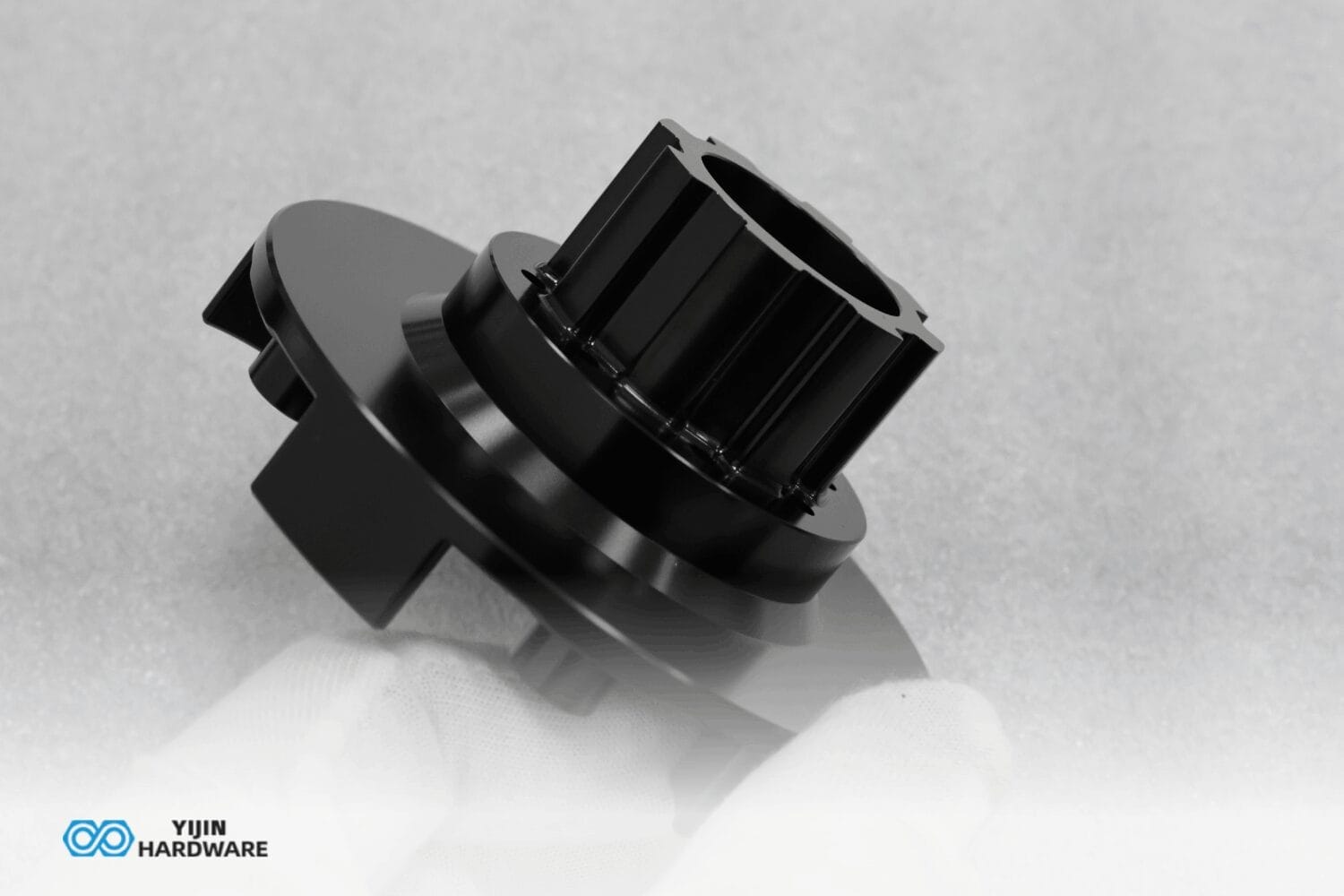

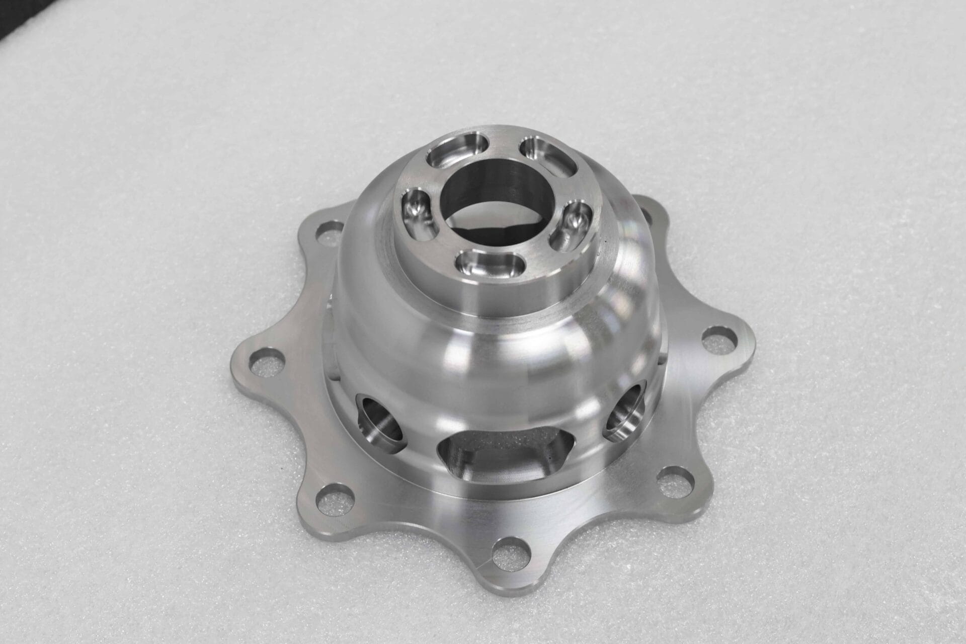
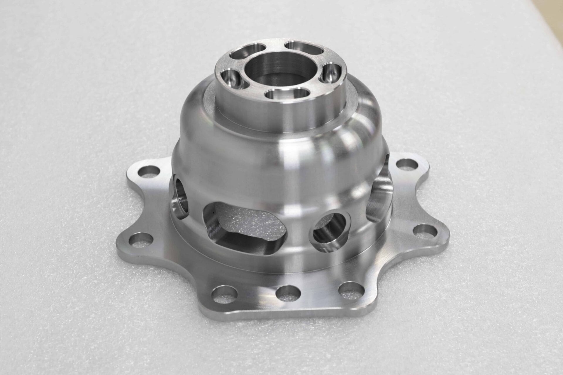
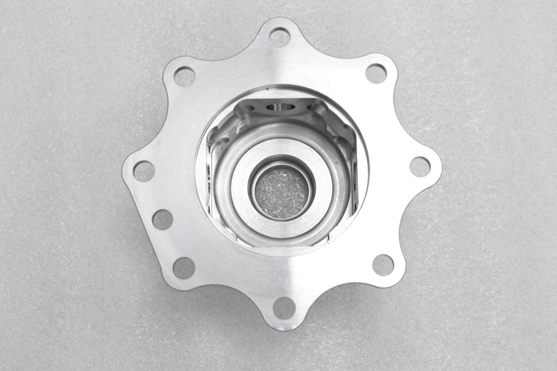
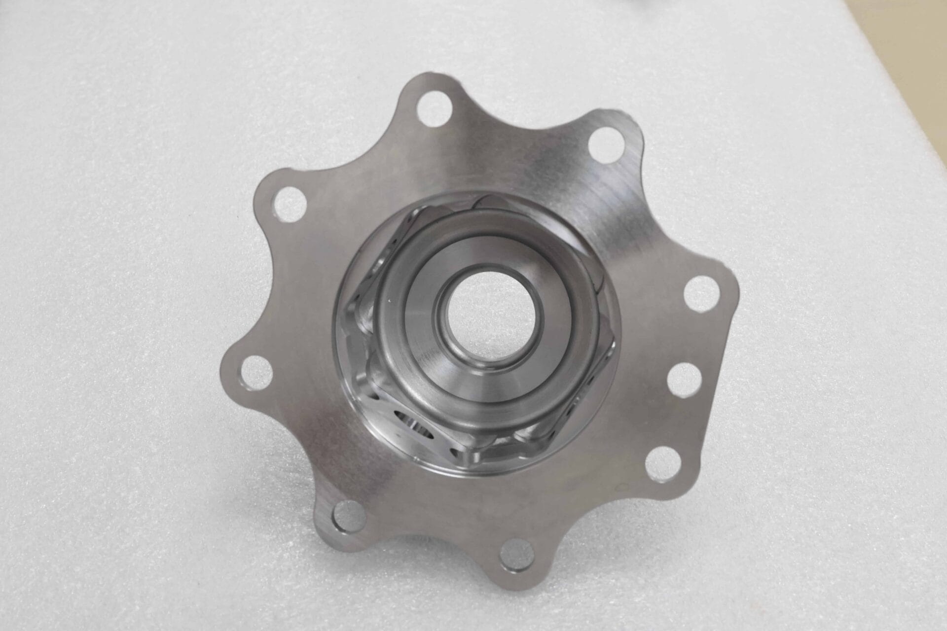
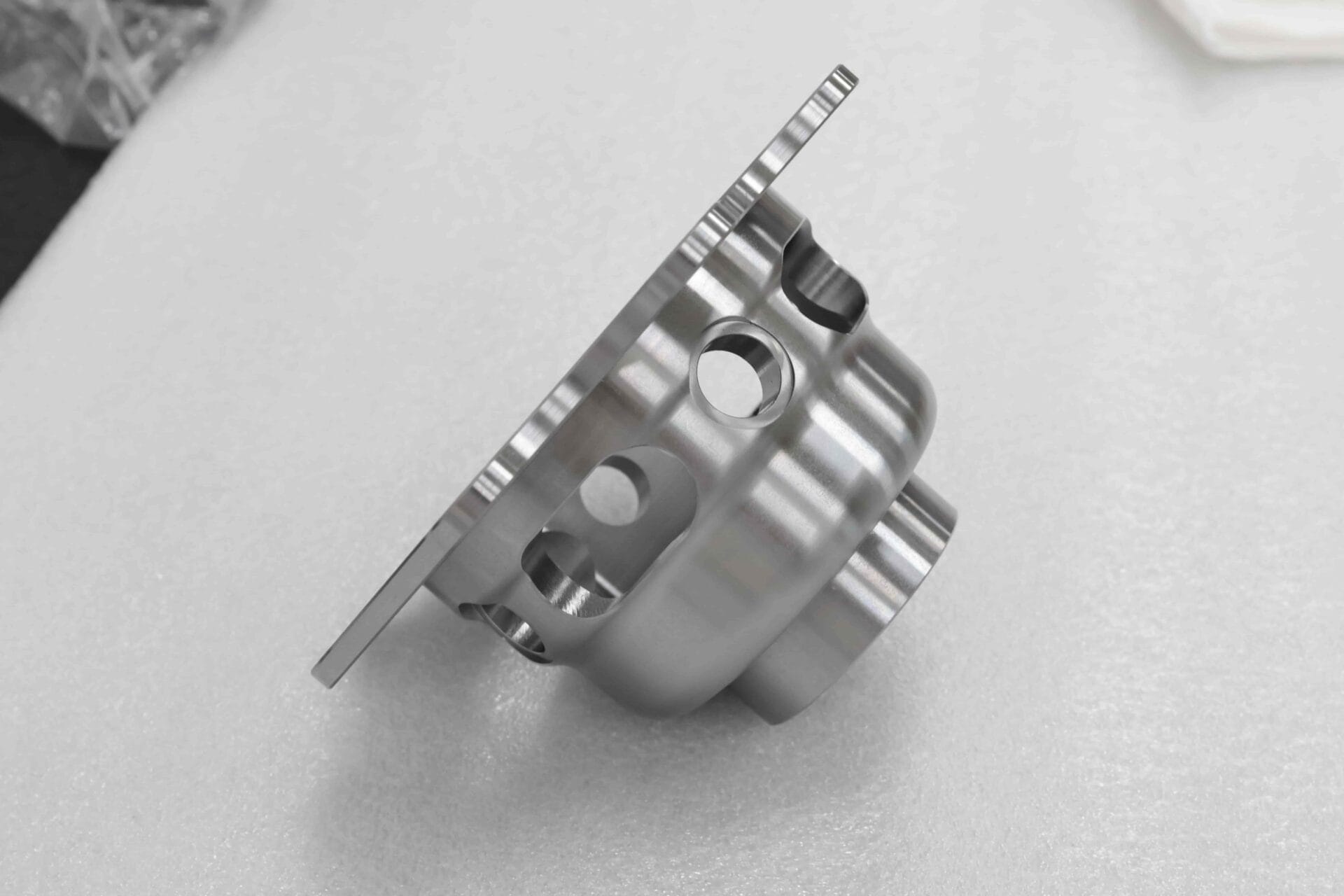
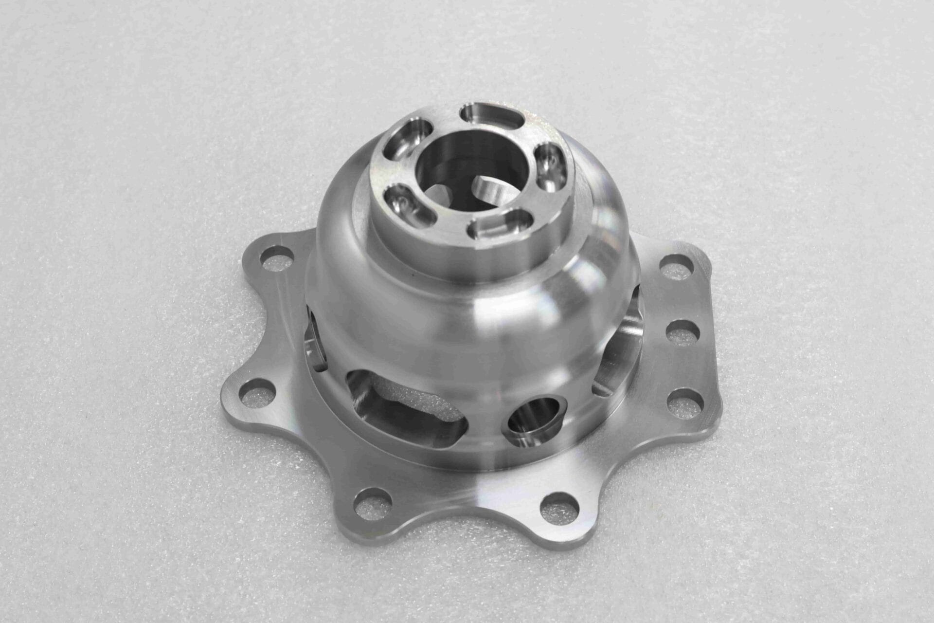
Dana, a global automotive powertrain supplier, needed a reliable machining partner for a custom 316 stainless steel wheel hub flange used in high-end electric vehicles. This component connects the electric drive half-shaft to the wheel hub and serves as a critical load-bearing part in the drivetrain system.
Because the part operates in coastal, high-salt-spray, high-vibration environments, it had to deliver both corrosion resistance and structural stability. At the same time, its critical mating features required extremely tight dimensional and geometric tolerances, with key surface errors controlled within ±0.005 mm.
However, the previous supplier was unable to meet the required accuracy consistently, which caused assembly interference, vibration, abnormal road-test noise, and repeated production delays.
| Item | Details |
|---|---|
| Industry | Automotive |
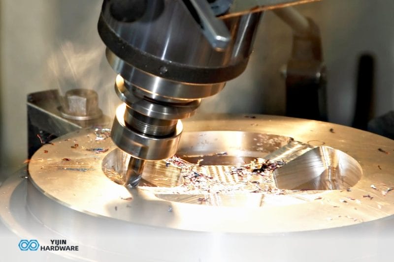
| Process | 5-axis CNC machining + in-process probing + CMM inspection |
| Material | 316 stainless steel |
| Use Case | High-precision, corrosion-resistant load-bearing hub flange |
The Challenge
1. 316 stainless steel was difficult to machine accurately
The material offered the corrosion resistance Dana needed, but it also created serious machining challenges. Its high viscosity, poor thermal conductivity, and strong cutting forces made it prone to built-up edge, tool wear, and thermal deformation.
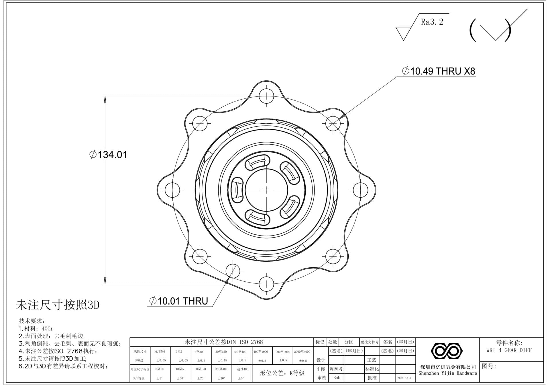
Using a standard three-axis machining setup, the previous supplier could not control the accuracy of key features such as the center locating hole, flange end face, and 8 mounting holes. Errors reached ±0.035 mm, far beyond the acceptable limit.
2. Low yield and repeated rework were disrupting the project
Because of deformation and flatness issues, the first-pass yield rate was only 72%. Around 28% of parts required rework, and each rework cycle added more than four days. This repeatedly delayed the customer’s SOP timeline and increased the risk of penalties and trust loss.
3. The customer needed more than basic machining
The original supplier could only machine to drawing and had no effective strategy for improving process stability. Dana needed a partner that could diagnose the root cause, optimize both the drawing and process, and deliver a repeatable precision solution for 316 stainless steel.
What the Customer Needed
Dana defined three clear goals for the project:
- Control critical dimensional errors within ≤ ±0.005 mm
- Increase first-pass yield to over 99% and eliminate rework
- Shorten delivery time by 20% while building a long-term precision machining solution for 316 stainless steel parts
Our Solution
To solve the problem, we built a closed-loop machining and quality control process tailored specifically for 316 stainless steel.
Preliminary Diagnosis: Accurately Identifying Material-Process Matching Issues
Failure component depth inspection
We first carried out full-dimensional inspection on three failed samples provided by the customer using a Zeiss coordinate measuring machine. The inspection results showed that the core errors were directly related to the machining characteristics of 316 stainless steel:
Cutting heat caused thermal deformation of the flange end face, resulting in a flatness deviation of 0.02 mm
Tool wear caused a maximum coaxiality deviation of 0.035 mm between the center hole and the flange end face
Uneven clamping force caused elastic deformation of the thin-walled structure, leading to an average positional deviation of 0.028 mm in the mounting holes
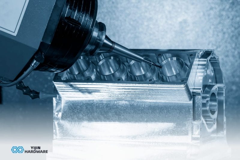
Process feasibility assessment
Based on the diagnosis, we selected the DMG MORI DMU 50 five-axis machining center, with spindle radial runout controlled within ≤0.001 mm, and combined it with a high-pressure cooling system. We then developed a dedicated machining strategy for 316 stainless steel based on the principles of low cutting force, slow feed, and layer-by-layer milling to reduce thermal deformation and tool wear.
Precision target breakdown
To improve process stability, we further broke down the customer’s final tolerance requirement into process-level targets. Rough machining allowance was set at 0.2 mm, semi-finishing allowance at 0.04 mm, and finishing tolerance was controlled within ±0.003 mm, allowing error to be gradually reduced across multiple stages.
Drawing Optimization: Deformation Control Design Adapted for 316 Stainless Steel
Design blind spot correction
To address the deformation risks caused by the characteristics of 316 stainless steel, we proposed three key design optimizations:
The original thin-walled area had no reinforcing ribs and was highly susceptible to deformation under cutting force. We added two symmetrical reinforcing ribs with a thickness of 2 mm to improve structural rigidity.
The original transition fillet radius of R0.8 had no clear tolerance limit. We optimized it to R1.2 ±0.02 mm to better disperse cutting stress and reduce deformation caused by stress concentration.
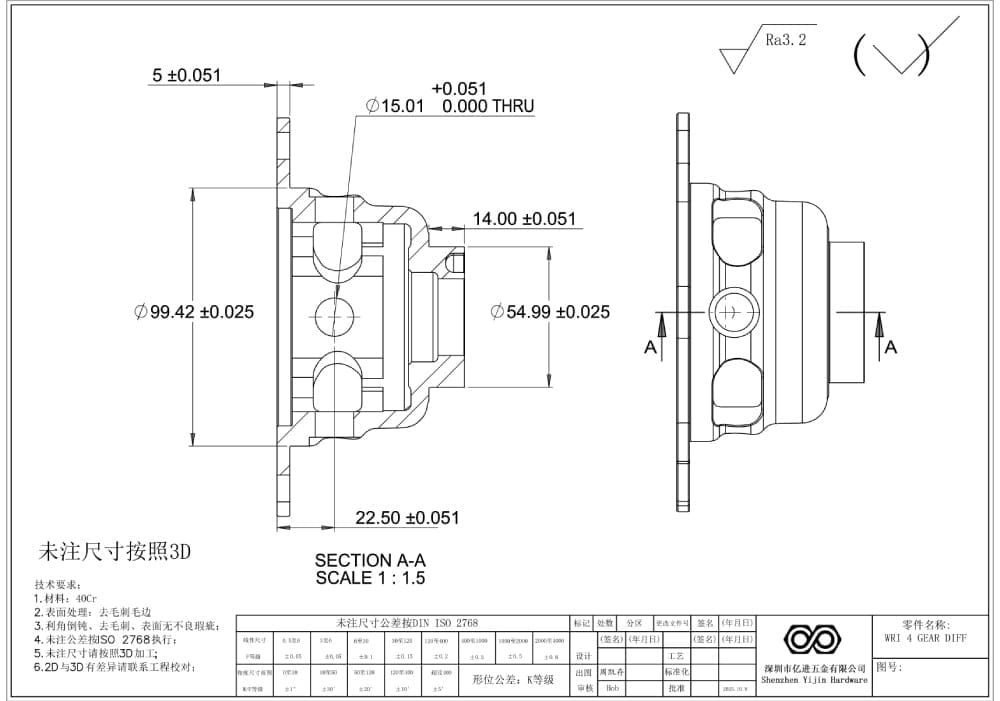
We clearly defined the machining datum as A Datum on the flange end face and specified that the coaxiality between the center hole and the end face must be controlled within ≤0.005 mm, avoiding datum confusion during machining and inspection.
Process adaptation adjustments
To better support the updated part design, we also adjusted the machining strategy. Single-sided milling was changed to symmetrical layered milling to reduce structural strain caused by unbalanced cutting force. In addition, the tool path was optimized to a climb milling + helical interpolation strategy to reduce vibration and minimize the risk of built-up edge formation.
Machining Execution: A Precision-Controlled Process for 316 Stainless Steel
Refined tool and parameter selection
To improve dimensional consistency and surface quality, we used different tools and cutting conditions for roughing, semi-finishing, and finishing:
Roughing: A φ16 mm carbide end mill with TiAlN coating and a stainless steel-specific cutting edge was used. Parameters were S = 2500 rpm, F = 300 mm/min, ap = 0.3 mm, ae = 6 mm, with 8 bar high-pressure emulsion coolant to remove excess material quickly while suppressing thermal deformation.
Semi-finishing: A φ10 mm carbide round nose cutter with a 0.02 mm edge chamfer was used. Parameters were S = 3500 rpm, F = 200 mm/min, ap = 0.15 mm, ae = 3 mm to improve contour accuracy.
Finishing: A φ6 mm mirror ball end mill made of ultra-fine-grain cemented carbide was used. Parameters were S = 4500 rpm, F = 100 mm/min, ap = 0.03 mm, ae = 0.08 mm, ensuring surface roughness of Ra ≤0.8 μm while minimizing cutting heat.
Process precision control
To keep the machining process stable, we applied the following controls throughout production:
Clamping: A customized hydraulic floating clamp was used, with clamping force controlled at 5 kN to prevent elastic deformation caused by rigid clamping.
Thermal control: The workshop was maintained at a constant temperature of 20 ±1°C. Before machining, the spindle was idled for 40 minutes for preheating. After every 5 parts, the process was paused for 1 minute to allow heat dissipation and reduce thermal deformation.
Online inspection: After every 5 parts, the diameter of the center hole and the position of the mounting holes were automatically checked using a Renishaw OMP40 probe, and tool wear was compensated in real time. This was especially important because tool wear when machining 316 stainless steel is around 3 times higher than for aluminum alloy.
Inter-process inspection: After roughing and semi-finishing, tool length and radius were checked with a tool setter. If the error exceeded ±0.002 mm, the tool was replaced immediately to avoid cumulative deviation.
Finished Product Inspection: Comprehensive Quality Verification of 316 Stainless Steel
Testing equipment and standards
Final inspection was carried out using a Zeiss CONTURA coordinate measuring machine with measurement accuracy of ±0.001 mm, strictly following the ISO 2768-2 precision standard. Probe pressure was adjusted to 0.5 N to avoid indentation on the 316 stainless steel surface.
Core inspection items
The final inspection focused on the following critical dimensions and geometric tolerances:
- Coaxiality between the center positioning hole and the flange end face (requirement ≤0.005 mm)
- Positional accuracy of the 8 sets of mounting bolt holes (requirement ≤0.005 mm)
- Flange end face flatness (requirement ≤0.003 mm)
- Surface roughness, roundness, and profile
Report output and traceability
A unique inspection report was generated for each product, including dimensional deviation curves and geometric tolerance cloud diagrams. Each report could be traced back to the machining process, operator, and equipment number, enabling full-chain quality traceability.
The Results
Precision performance exceeded the target
The final parts achieved stable critical dimensional control within ±0.003 to ±0.005 mm.
Key results included:
- Center hole coaxiality improved to an average of 0.004 mm
- Mounting hole positional deviation controlled within ≤0.004 mm
- Flange end face flatness improved to ≤0.002 mm
These improvements fully resolved the previous assembly interference issue and eliminated the abnormal vibration and noise seen during road testing.
Yield and delivery performance improved significantly
The production outcome was not only more accurate, but also far more stable and efficient.
- First-pass yield increased from 72% to 99.8%
- Rework rate dropped to 0%
- Batch production lead time was reduced from 16 days to 12.8 days
- Overall delivery time improved by 20%
- Per-unit manufacturing cost was reduced by 10%
- Rework-related cost was eliminated completely
The project expanded into long-term cooperation
Because of the success of this project, Dana extended the relationship beyond the original flange program. We went on to receive machining orders for three additional 316 stainless steel electric drive components, including:
- Electric drive end cover
- Half-shaft sleeve
- Differential bracket
As a result, annual order volume increased by 60%, and we became a long-term strategic machining partner for this customer.
Why this Project Matters
This case shows that high-precision machining of difficult materials like 316 stainless steel is not just about using better equipment. The real breakthrough comes from combining:
- Material-specific process planning
- DFM-driven drawing optimization
- Controlled clamping and thermal management
- In-process inspection and compensation
- Full final inspection with traceability
When these steps work together, it becomes possible to achieve both tight tolerances and stable production performance, even on corrosion-resistant, thin-walled automotive parts.
Applications for Similar Projects
This solution is especially relevant for customers who need:
- High-precision stainless steel parts for automotive, marine, or medical applications
- Thin-wall or complex structural components with strict dimensional requirements
- Better yield, less rework, and shorter lead times for difficult-to-machine materials such as 316 or 304 stainless steel
Conclusion
For Dana, this project was not only about machining one flange correctly. It was about solving a recurring production problem at the process level.
By combining five-axis machining, material-adapted process control, design optimization, and full-chain quality management, we helped the customer turn an unstable, high-risk part into a reliable production component. The result was higher precision, faster delivery, lower total cost, and a stronger long-term supply relationship.
From design review to machining and inspection, Yijin Solution helps customers improve manufacturability, control quality, and reduce production risk. We support complex metal parts that require tight tolerances, consistent results, and reliable delivery across prototyping and production. Start Your Next Project with Yijin Solution
Back to Top: How We Helped an Automotive Supplier Machine a 316 Stainless Steel Hub Flange to ±0.005 mm