
Bettinardi Golf is a globally recognized high-end golf equipment brand known for the development and production of hand-polished golf putters. The brand has extremely demanding standards for component precision, surface texture, and assembly compatibility.
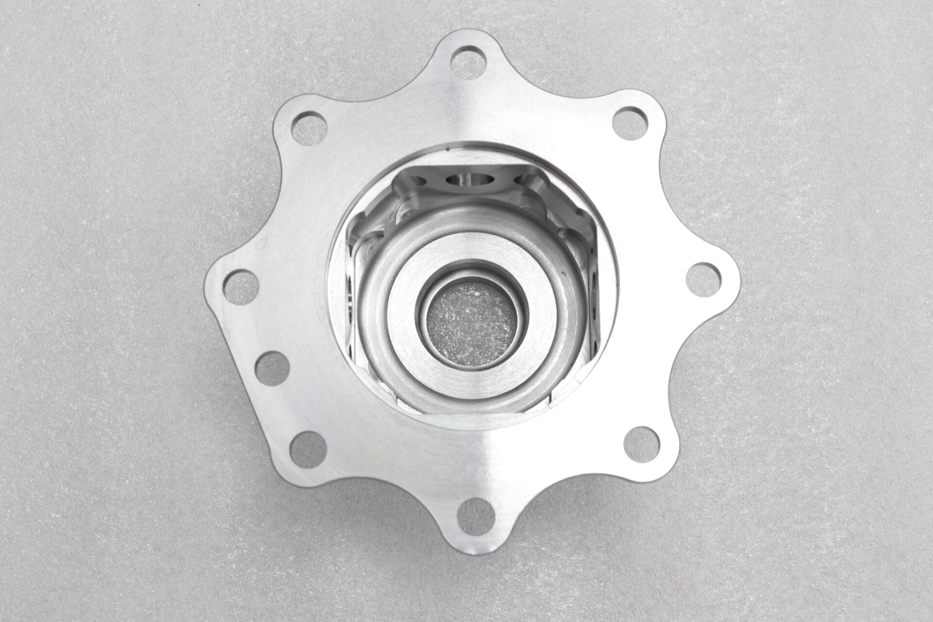
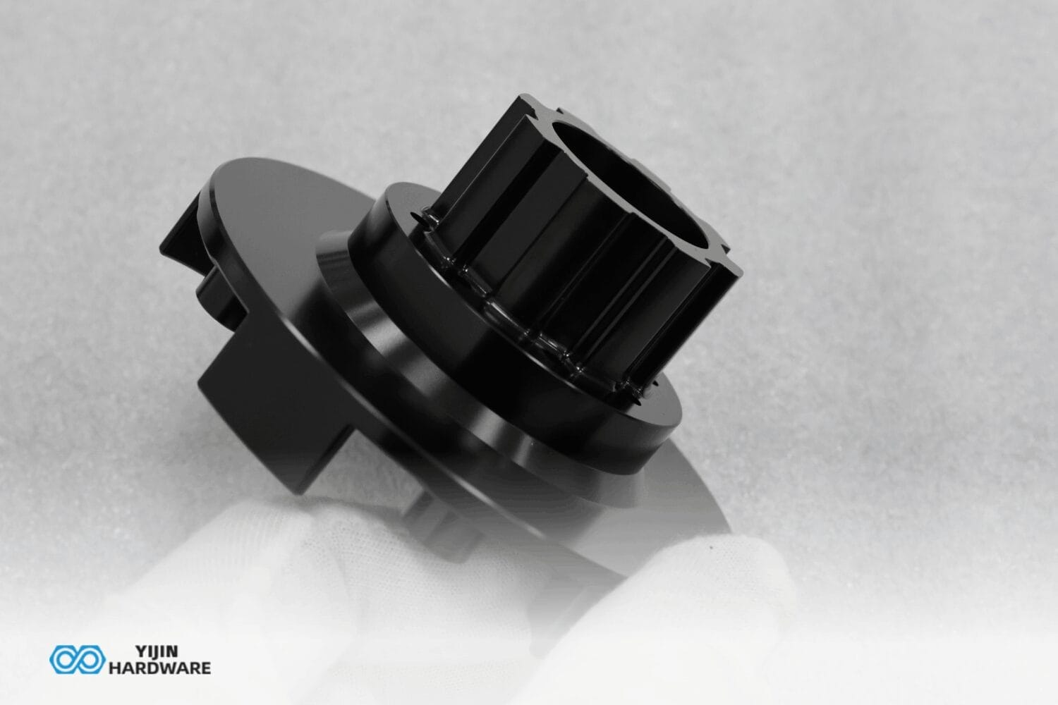
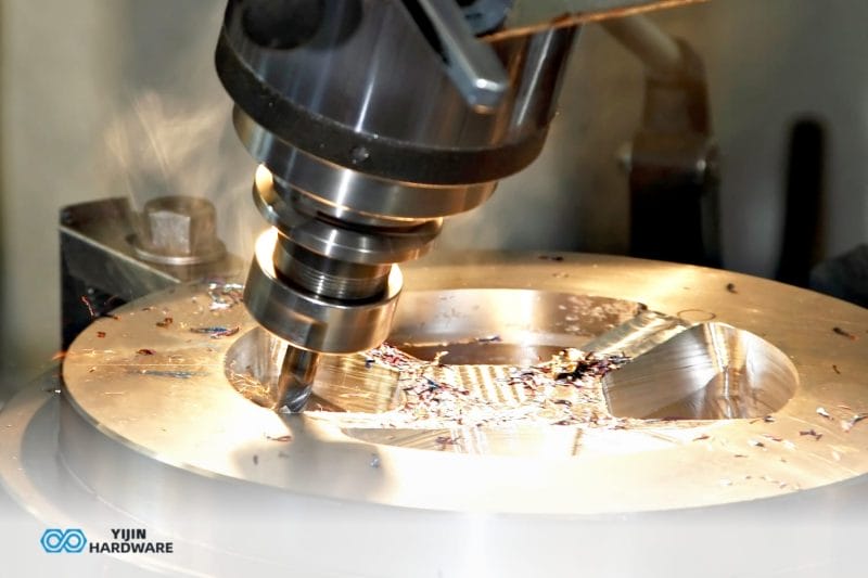
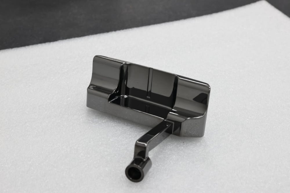
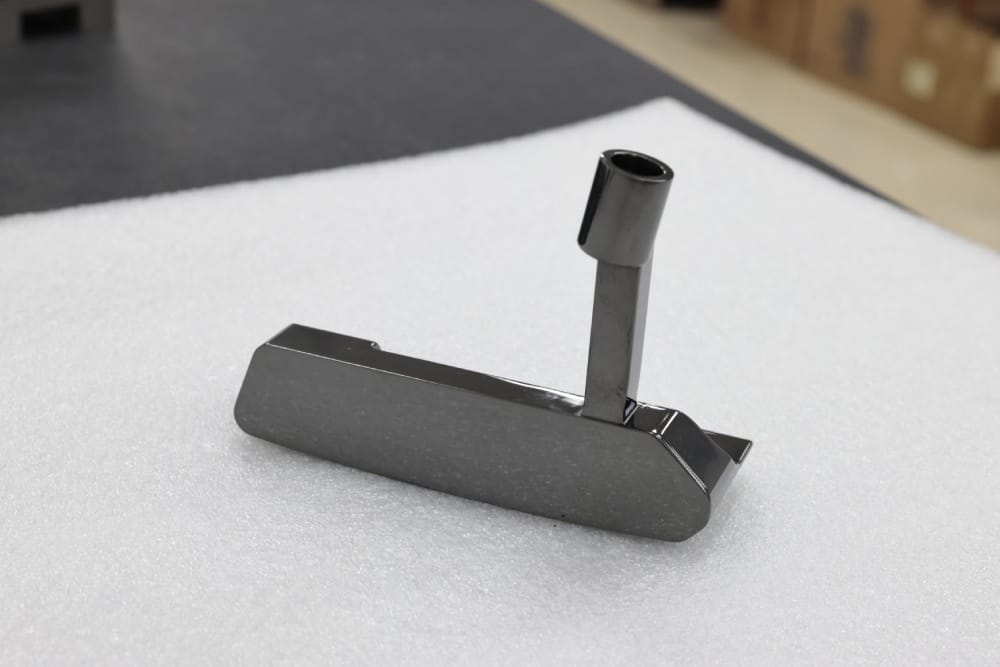
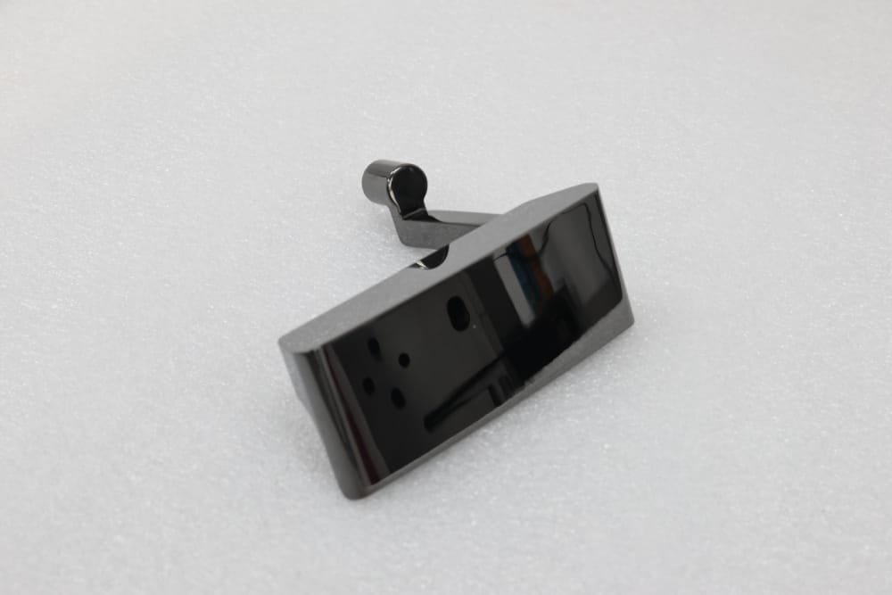
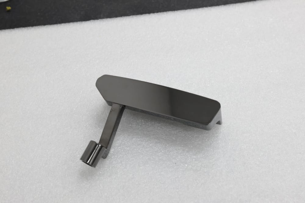
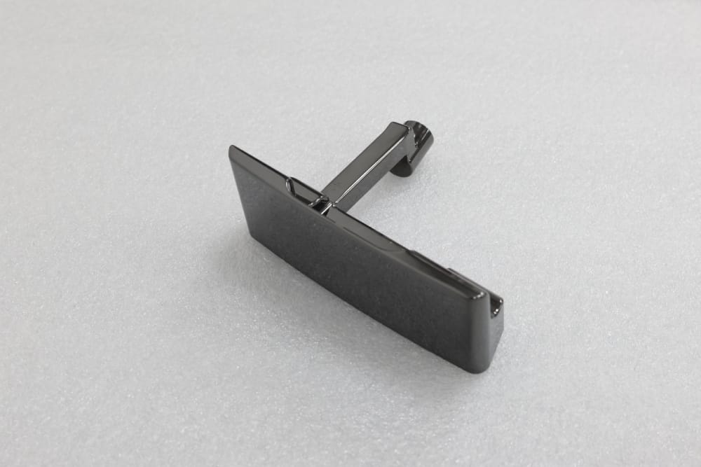
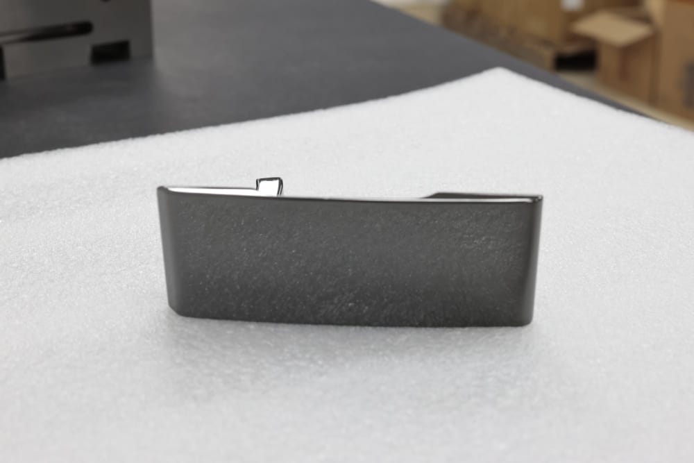
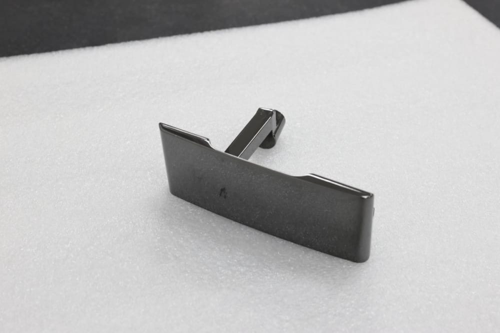
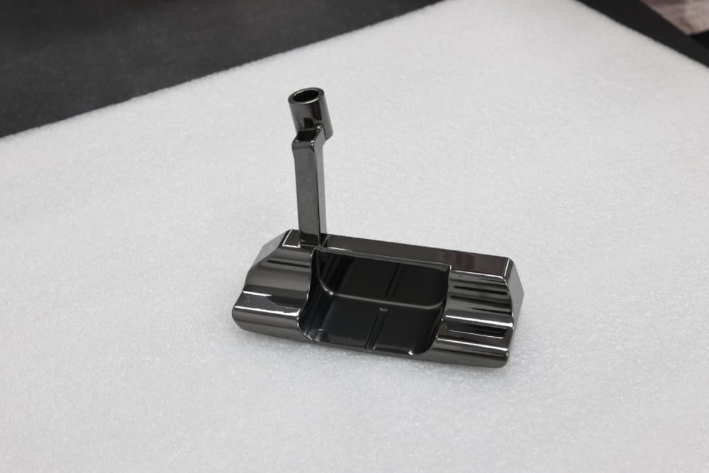
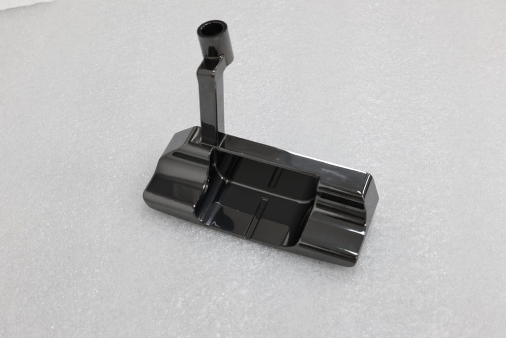
This project focused on a main component of a golf putter head made of 304 stainless steel. The part required a high-gloss polished surface followed by black PVD treatment. Structurally, it included multi-curved surfaces, deep cavity grooves, and an irregular connecting shank, making it both a critical load-bearing component and a highly visible aesthetic feature of the putter.
Before working with us, the client had already approached two CNC machining suppliers for trial production, but neither supplier passed the acceptance test. At that point, the customer was already facing a serious delivery risk for the new product launch.
| Item | Details |
|---|---|
| Industry | Sports Equipment |
| Process | 5-axis CNC machining + polishing + black PVD coating + full inspection |
| Material | 304 stainless steel |
| Use Case | High-precision, high-aesthetic main structural component for a golf putter head |
The Challenge
The client’s difficulties were not limited to machining alone. The project involved a combination of design feasibility, structural precision, appearance consistency, and delivery pressure.
1. Design and manufacturing were seriously disconnected
The customer’s original drawings were created by the product design team without fully considering CNC machining feasibility. As a result, the design contained clear manufacturability blind spots, especially in the multi-curved transition areas and deep cavity sidewalls. Standard cutting tools could not enter these areas without interference, which meant the previous suppliers were unable to complete even the basic roughing process.
2. Structural precision issues were significant
The original drawings did not clearly define process datums or the tolerance chain. Critical requirements such as the coaxiality of the connecting handle and the depth of the cavity were vaguely specified. At the same time, stainless steel is prone to stress deformation during machining. As a result, the dimensional deviation after machining exceeded 0.03 mm, which could not meet the assembly requirements of the rod body.
3. Appearance quality and surface texture could not be guaranteed
The original curved design also created polishing dead corners, with a high risk of residual tool marks. After PVD coating, the part was likely to show uneven gloss, edge color variation, and other appearance defects, which did not align with Bettinardi Golf’s high-end product standards.
4. Delivery pressure was becoming critical
The client was already under pressure from a tight new product launch schedule. Multiple rounds of failed trial production and rework had delayed progress. They urgently needed a supplier that could solve the issues from the design stage onward, rather than only attempting to machine the part as drawn.
What the Customer Needed
To move the project forward, the customer required a supplier that could provide both engineering optimization and stable manufacturing execution. The key expectations were:
A professional engineering team to optimize the product design and drawings, eliminate machining blind spots, and clarify process and inspection standards
High-precision CNC machining for complex multi-curved and deep-cavity structures, with stainless steel deformation controlled and dimensional tolerance kept within ≤ ±0.01 mm
Stable surface quality after polishing and reliable PVD coating compatibility, so the product could pass both assembly inspection and appearance inspection in one go
A shorter processing cycle, lower time cost, and the potential to build a long-term supplier relationship
Our Solution
The core of the solution was a dual-dimensional optimization approach, combining design and drawing optimization with close collaboration between structural engineers and appearance engineers.
1. Pre-Design DFM Review: Structural and Appearance Engineers Diagnosed the Problem from Two Dimensions
We immediately formed a dedicated project team made up of senior structural engineers and high-end appearance engineers, combining more than 10 years of experience in precision sports equipment manufacturing. Together, they carried out a comprehensive DFM (Design for Manufacturability) analysis of the client’s original drawings.
From the structural engineer’s perspective
The review focused on identifying manufacturability blind spots, structural stress concentration areas, and missing process references. Three core machining obstacles were identified:
- The deep cavity sidewall inclination angle was too small at 3°
- The curvature transition across multi-curved surfaces changed too abruptly
- The coaxiality reference of the connecting handle was ambiguous
From the appearance engineer’s perspective
The appearance-focused review evaluated both polishing feasibility and the final visual effect after PVD coating. Two main appearance risks were identified:
- Tool marks were likely to remain in curved corner areas
- Sharp edges could easily cause coating color differences and uneven polishing allowance distribution
Collaborative review output
Based on the joint review, we produced a DFM Analysis Report that clearly identified which areas of the original design were:
- Unmanufacturable
- Unable to maintain controllable precision
- Likely to create appearance defects
This report provided a clear basis for the next stage of optimization.
2. In-Depth Structural Design Optimization: Solving the Core Problems of Machinability and Stable Precision
To address the design’s manufacturability and precision weaknesses, the structural engineering team systematically reconstructed and optimized the original drawings.
Deep cavity accessibility optimization
The original deep cavity sidewall inclination angle was changed from 3° to 5°, and the bottom fillet radius was adjusted from R0.3 mm to R0.8 mm. These changes maintained structural strength while allowing the five-axis tool to enter the cavity without interference. At the same time, the chip evacuation path was optimized to prevent iron filings from scratching the inner wall.
Multi-surface transition smoothing
The curvature radius in the multi-surface transition area was redesigned. The original abrupt transition of R0.5 mm was optimized into a more gradual R1.2 mm transition. This reduced cutting vibration and stress concentration and helped control stainless steel deformation within 0.005 mm.
Process benchmarks and tolerance chain reconstruction
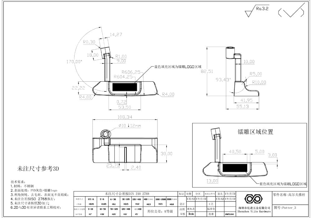
To make accuracy control more reliable throughout the process, we rebuilt the datum system and tolerance logic:
The rod mounting hole was defined as the core reference, and key dimensional tolerances were redefined, including:
- Connecting handle coaxiality: ≤0.008 mm
- Cavity depth: ±0.01 mm
- Surface profile: ≤0.005 mm
Machining datum surfaces and inspection datum surfaces were added to the drawing set, preventing ambiguity during both machining and inspection and ensuring the full process remained controllable.
Stress relief design
In areas prone to deformation, a more symmetrical structural design was adopted. A 0.1 mm stress relief margin was reserved, and low-temperature aging treatment was introduced during the process to suppress stainless steel stress deformation at the structural level.
3. Appearance Design and Surface Process Optimization: Solving the Core Problems of Surface Texture and High-End Aesthetics
Taking both polishing behavior and PVD coating characteristics into account, the appearance engineering team made targeted refinements to the product’s visible surfaces.
Surface smoothness optimization
The direction and continuity of multiple curved surfaces were re-evaluated to eliminate polishing dead corners present in the original design. This ensured that polishing tools could fully cover all relevant surfaces and minimized the risk of local tool mark retention.
Precise polishing allowance allocation
To balance cosmetic quality with dimensional control, polishing allowance was allocated by surface priority:
0.15 mm allowance was reserved for appearance display surfaces, while 0.1 mm was reserved for stress-bearing structural surfaces. This ensured the final polished surface could meet Ra0.15 μm without compromising key dimensions.
Edge chamfering was also optimized. The original sharp edges were changed to R0.2 mm rounded corners, improving hand feel while reducing the risk of edge color difference and film build-up after PVD coating.
PVD compatibility verification
The PVD coating process was simulated in advance, and requirements for substrate roughness and cleanliness were optimized accordingly. This helped ensure the base surface remained free from scratches and impurities so the final coating could present a uniform, high-gloss black appearance consistent with Bettinardi Golf’s premium brand image.
4. Drawing Reconstruction and Process Documentation Output: Making the Optimization Results Executable and Traceable
After the design optimization was completed, the engineering team rebuilt the production documentation so the optimized solution could be implemented consistently.
3D model and 2D drawing reconstruction
Based on the optimized design, we redrew the parametric 3D model and the clearly annotated 2D engineering drawings, supplementing all process references, tolerance requirements, and surface treatment specifications.
Machining process guidance documents
For five-axis CNC machining, we produced dedicated documentation covering:
- Toolpath recommendations
- Cutting parameter recommendations
- Process sequence descriptions
This allowed the production team to implement the optimized design directly and consistently.
Inspection standard documents
We also clearly defined inspection points and acceptance criteria for both coordinate measuring machines and laser surface scanners, ensuring that final inspection fully matched the optimized design requirements.
Customer confirmation
Before production began, we submitted a Design Optimization Comparison Report to the client. This report visually showed:
- The structural differences before and after optimization
- The improvement in machining feasibility
- The improvement in appearance quality and surface texture
Production started only after receiving the customer’s signed approval.
Processing Technology and Quality Control
Once the design optimization and document reconstruction were completed, we moved into controlled production and quality assurance.
1. Customized Five-Axis Machining Process
Based on the optimized drawings, we used a five-axis CNC machining center together with stainless steel carbide coated tools. For the deep cavities and curved surfaces, a layered progressive milling process was adopted to reduce tool vibration and stress deformation.
During the finishing stage, high-speed, shallow-depth cutting was used to ensure the machined surface roughness reached below Ra0.2 μm, creating the right foundation for the subsequent polishing process.
2. End-to-End Quality Control
To ensure stable accuracy and visual consistency, quality control was embedded into every production stage.
Dedicated engineer for each process
Each stage—including roughing, semi-finishing, finishing, and polishing—was assigned to a dedicated process engineer. Machine load and vibration data were monitored in real time, and cutting parameters were adjusted as needed.
Online real-time inspection
Key dimensions such as:
- Connecting handle coaxiality
- Cavity depth
- Surface profile
were checked using online inspection equipment. Accuracy verification was completed after each part was processed, preventing cumulative deviation.
Full-dimensional final inspection
Final inspection was carried out using a coordinate measuring machine, laser surface scanner, and surface roughness tester. A 100% inspection standard was applied to dimensional accuracy, surface quality, and assembly fit to ensure the product could pass acceptance on the first attempt.
Results
1. Design and manufacturing challenges were fully resolved
The optimized design completely eliminated machining blind spots, allowing the five-axis tool to machine all areas without interference. As a result, product yield increased from 65% during the earlier supplier trial stage to 98%.
At the same time, all key dimensions met the required precision standards:
- Connecting handle coaxiality: ≤0.008 mm
- Surface profile: ≤0.005 mm
These results fully met the assembly requirements of the rod body.
In terms of surface quality, the part achieved Ra0.15 μm after polishing, and after PVD coating, the appearance remained uniform and defect-free, successfully passing both the customer’s appearance inspection and assembly inspection.
2. Efficiency and cost were significantly improved
Compared with the suppliers previously used by the customer:
- Processing efficiency increased by 40%
- The single-piece processing cycle was shortened from 12 days to 9 days
- Total delivery time was reduced by 25%
By avoiding repeated rework and trial losses, the overall production cost was reduced by 18%, significantly easing both the scheduling pressure and financial burden associated with the customer’s new product launch.
3. The project led to long-term cooperation and industry recognition
After the success of this project, the customer entrusted us not only with this putter component, but also with all subsequent complex putter-related parts, including putter heads and counterweights, helping establish our position as a core strategic supplier.
Because of the breakthroughs achieved in both design optimization and precision machining, the client also proactively recommended our services to other leading golf equipment brands such as Titleist and Callaway, helping us expand our presence in the field of high-end sports equipment precision machining.
Conclusion
This case was not simply about machining a difficult stainless steel part. It was about solving all three major barriers that often prevent complex high-end sports equipment components from being delivered successfully: difficult design, difficult manufacturing, and high precision requirements.
The key to the project was the combination of:
- Structural engineer input for manufacturability and precision control
- Appearance engineer input for surface texture and PVD compatibility
- Integrated execution from DFM review and design optimization through to machining, polishing, and full inspection
This end-to-end approach allowed us to bridge the gap between industrial design intent and actual manufacturable quality. It also shows why customers developing complex premium components often need more than a CNC supplier. They need an engineering partner that can optimize design, stabilize production, and protect final product quality from the beginning.
When internal resources are stretched, previous suppliers cannot meet the quality target, or complex designs create machining and finishing risks, Yijin Solution helps bridge the gap from design intent to stable production. From DFM analysis and drawing optimization to precision CNC machining, polishing, coating, and full inspection, we help customers bring complex metal parts to market with better quality control, faster execution, and greater manufacturing confidence. Start Your New Project with Yijin Solution
Back to Top: How We Solved Design, Machining, and Precision Challenges for a Complex Golf Putter Component