CNC machining tolerances in mm define the acceptable dimensional variation in manufactured parts. These precise specifications are critical for ensuring parts function correctly, fit together properly, and can be produced cost-effectively. For engineers and designers, understanding machining part tolerances prevents costly manufacturing errors and assembly problems.
This comprehensive guide covers everything from basic tolerance definitions to advanced applications, helping you make informed decisions for your next CNC machining project. Whether you’re designing precision aerospace components or consumer products, mastering tolerance specification is essential for successful manufacturing.
Key Takeaways
- Standard CNC machining tolerances typically range from ±0.05 mm to ±0.13 mm, depending on the specific manufacturing process
- Tighter tolerances increase costs exponentially, with costs rising 15-30% for tolerances of ±0.05 mm versus standard ±0.13 mm
- Material properties significantly impact achievable tolerances, with metal parts generally allowing tighter tolerances than plastic parts
- Only specify a tight tolerance for critical functional features to optimize manufacturing costs and production time
- GD&T provides more comprehensive control over part geometry than traditional dimensional tolerances
What are CNC Machining Tolerances and Why do they Matter?
CNC machining tolerance is the permissible dimensional variation in manufactured parts. This specification directly determines how closely a machined part must match its design dimensions. Machining tolerances matter because they control three critical aspects: functional performance, assembly fit, and manufacturing costs.
When specifying tolerances for CNC milling or other machining processes, overly tight requirements significantly increase production costs, while excessively loose tolerances lead to poor-fitting or non-functional components.
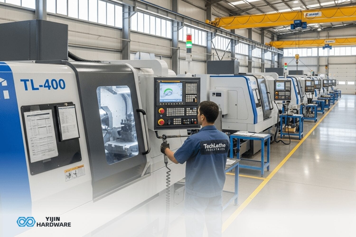
Looking for CNC milling China manufacturing services? Yijin Hardware offers precise and cost-effective CNC milling solutions, ensuring that your projects meet the necessary tolerances while maintaining high-quality standards.
How are CNC Machining Tolerances Defined?
CNC machining tolerances are defined as the allowable dimensional deviation from nominal values. These specifications appear as bilateral tolerance (±0.1 mm), unilateral tolerance (+0.1/-0 mm), or limit tolerance (10.1 mm to 9.9 mm). The tolerance value directly indicates manufacturing precision requirements—smaller values demand higher precision.
In metric specifications, tolerances are measured in millimeters (mm), with values typically ranging from ±0.05 mm to ±0.5 mm. International standards like ISO 2768 provide standardized tolerance frameworks that ensure consistency across the manufacturing industry. These standards define tolerance classes based on precision requirements.
Tolerance Expression Methods
The main methods for expressing tolerances in CNC machining documentation are through bilateral tolerance, unilateral tolerance, limit tolerance, and decimal places:
- Bilateral tolerance: Equal variation in both directions (e.g., 10 mm ±0.1 mm)
- Unilateral tolerance: Variation in only one direction (e.g., 10 mm +0.1/-0 mm)
- Limit tolerance: Specific upper limit and lower limit (e.g., 10.1 mm – 9.9 mm)
- Decimal Places: More decimal places indicate tighter tolerances for machined parts
What are the Different Types of Tolerances Used in CNC Machining?
The main types of tolerances in CNC machining include bilateral, unilateral, and limit tolerances, each serving different design purposes. Bilateral tolerance allows variation in both positive and negative directions from the nominal dimension, offering manufacturing flexibility while maintaining functional requirements.
Unilateral tolerance permits deviation in only one direction from the basic dimension, ensuring critical size constraints are maintained. This type is ideal for components that must fit together within assemblies, where either the maximum or minimum dimension is critical to proper function.
Advanced Tolerance Systems
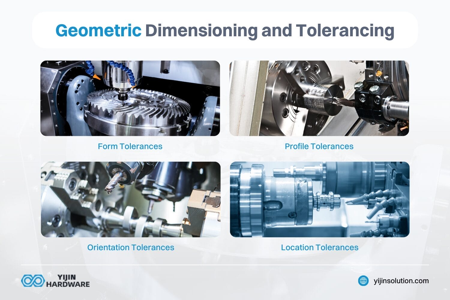
Geometric dimensioning and tolerancing (GD&T) is a comprehensive tolerance system that controls not just dimensions but also form, orientation, and position characteristics. GD&T provides superior control over complex part geometry through a standardized symbolic language developed by the American Society of Mechanical Engineers. According to the Universal Technical Institute, GD&T ensures accuracy and precision in CNC manufacturing. It does this by specifying the form, orientation, and location of features on a part.
| Tolerance Type | Symbol | Application | Example |
|---|---|---|---|
| Flatness | ⃞ | Surface evenness | 0.05 mm flatness for sealing surfaces |
| Straightness | ― | Linear element control | 0.02 mm straightness for guide rails |
| Cylindricity | ○ | Cylindrical form | 0.03 mm cylindricity for bearings |
| True position | ⌖ | Feature location | 0.08 mm true position for mounting holes |
| Parallelism | ∥ | Surface alignment | 0.04 mm parallelism for mating faces |
| Concentricity | ◎ | Coaxial alignment | 0.06 mm concentricity for rotating parts |
What are Standard Tolerances for CNC Machining in Millimeters?
Standard tolerance for CNC machining is ±0.13 mm (±0.005″) for most milling and turning operations. This precision level represents the baseline capability of modern CNC equipment and provides sufficient accuracy for most general applications without requiring specialized processes or equipment.
The table below provides a comprehensive reference for typical CNC machining tolerances across various processes:
| CNC Process | Standard Tolerance (mm) | Standard Tolerance (inch) |
|---|---|---|
| Milling (3-axis) | ±0.13 mm | ±0.005” |
| Milling (5-axis) | ±0.13 mm | ±0.005” |
| Turning/Lathe | ±0.13 mm | ±0.005” |
| Router | ±0.13 mm | ±0.005” |
| Gasket Cutting | ±0.762 mm | ±0.030” |
| Screw Machining | ±0.13 mm | ±0.005” |
| Engraving | ±0.13 mm | ±0.005” |
ISO 2768 Standard Tolerance Classes
ISO 2768 is an international standard that defines four general tolerance classes for machined parts:
- Fine (f): For high precision work (e.g., ±0.05 mm for dimensions up to 30 mm)
- Medium (m): For general precision work (e.g., ±0.1 mm for dimensions up to 30 mm)
- Coarse (c): For lower precision work (e.g., ±0.2 mm for dimensions up to 30 mm)
- Very Coarse (v): For rough work (e.g., ±0.5 mm for dimensions up to 30 mm)
At Yijin Hardware, our DMG Mori and Haas CNC machines achieve ISO 2768 Fine tolerance class specifications for critical components requiring high dimensional accuracy.
How do Materials Affect Achievable Tolerances?
Materials directly determine achievable tolerances through their inherent properties like hardness, thermal stability, and machinability. Metal parts generally allow tighter tolerances than plastic parts due to their dimensional stability during machining. Aluminum and steel typically maintain tolerances of ±0.13 mm under standard machining conditions.
Plastic parts present greater tolerance challenges due to thermal sensitivity, flexibility, and moisture absorption. Standard tolerances for plastics are typically wider at ±0.25 mm (±0.010″) to accommodate these material characteristics. Temperature variations during machining can cause significant dimensional shifts in plastic components.
Material-Specific Tolerance Considerations
The following summarizes how different materials affect achievable tolerances in CNC machining:
- Aluminum Alloys: Excellent machinability with achievable tolerances of ±0.05 mm
- Steel Alloys: Good dimensional stability with achievable tolerances of ±0.08 mm
- Stainless Steel: More difficult to machine, with typical tolerances of ±0.10 mm
- Brass/Copper: Good machinability with achievable tolerances of ±0.05 mm
- Engineering Plastics: Require wider tolerances of ±0.15 mm to ±0.25 mm
- Titanium Alloys: Difficult to machine with typical tolerances of ±0.13 mm
What Factors Influence CNC Machining Tolerance Capabilities?
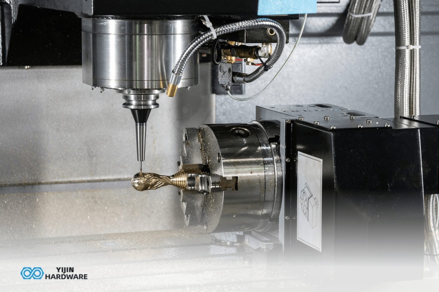
Multiple factors determine achievable tolerances in CNC machining, with machine quality being the primary influence. High-precision machining centers with rigid construction, thermal stability, and advanced control systems maintain tighter tolerances than basic equipment. Cutting tool selection also significantly impacts tolerance capabilities.
Tool wear, deflection, and geometry directly affect dimensional accuracy, making high-quality carbide tools essential for maintaining tight tolerances. For a precision aerospace component with ±0.02 mm tolerance requirements, Yijin Hardware uses premium solid carbide end mills with specialized coatings and rigorous tool condition monitoring to ensure dimensional accuracy throughout production.
Critical Tolerance Factors
Machine rigidity, thermal stability, toolpath strategy, and other factors have the greatest impact on achievable tolerances in CNC machining:
- Machine Rigidity: Resistance to deflection under cutting forces
- Thermal Stability: Consistency of dimensions despite temperature changes
- Toolpath Strategy: Appropriate cutting approaches for feature types
- Cutting Parameters: Speed, feed, and depth settings optimized for precision
- Workholding Methods: Secure fixturing that minimizes vibration
- Tool Condition Monitoring: Real-time adjustment for tool wear compensation
How much do Tighter Tolerances Increase Manufacturing Costs?
Tighter tolerances directly increase manufacturing costs due to additional resources required for higher precision. Parts with tolerances of ±0.05 mm typically cost 15-30% more than those with standard tolerances of ±0.13 mm due to longer cycle times, additional setups, and more frequent tool changes.
The cost-tolerance relationship is non-linear, as tolerances tighten below ±0.025 mm, costs rise exponentially. This occurs because ultra-precision machining requires specialized equipment, enhanced quality control processes, and potentially multiple operations to achieve final dimensions. For a stainless steel medical component, moving from ±0.05 mm to ±0.01 mm tolerance increased production costs by 45%.
Cost Impact of Tolerance Specifications
The table below illustrates how different tolerance specifications affect manufacturing costs:
| Tolerance Range | Cost Impact | Machine Requirements | Inspection Needs |
|---|---|---|---|
| ±0.25 mm and above | Baseline cost | Standard CNC | Basic inspection |
| ±0.13 mm to ±0.25 mm | 5-10% increase | Standard CNC | Regular inspection |
| ±0.05 mm to ±0.13 mm | 15-30% increase | High-precision CNC | C mm verification |
| ±0.025 mm to ±0.05 mm | 30-50% increase | Premium CNC | 100% inspection |
| Below ±0.025 mm | 50-100% increase | Ultra-precision CNC | Advanced metrology |
When Should You Specify Tighter Tolerances?
You should specify tighter tolerances only for features that directly impact part functionality or assembly fit. Critical mating surfaces, bearing seats, precision alignment features, and sealing surfaces typically require tighter tolerances to ensure proper operation. For non-critical features, standard tolerances provide sufficient accuracy at a lower cost.
In aerospace and medical applications, tight tolerances are often necessary for safety-critical components. For example, a medical implant may require ±0.01 mm tolerances on articulating surfaces to ensure proper function and longevity, while non-functional features can use standard ±0.13 mm tolerances to reduce manufacturing costs.
How does GD&T Compare to Traditional Tolerancing?
GD&T tolerances provide superior control over part geometry compared to traditional plus/minus tolerancing. Traditional tolerancing only controls size dimensions, while GD&T addresses form, orientation, location, and runout characteristics through a standardized symbolic language. This comprehensive approach ensures parts function correctly in their assembled state.
GD&T offers significant advantages by controlling the relationships between features and establishing datum reference frames. This system allows for maximum material condition (mmC) and least material condition (LMC) specifications that provide bonus tolerance when parts deviate from their maximum material size, potentially reducing manufacturing costs while maintaining functional requirements.
What is Yijin Hardware’s Thermal Stability Compensation Method?
Yijin Hardware’s proprietary thermal stability compensation system achieves tolerances as small as ±0.005 mm in production environments. This advanced system combines real-time temperature monitoring with predictive expansion models to adjust machining parameters dynamically during the cutting process. By compensating for thermal growth in both the machine and workpiece, we maintain exceptional precision even during extended operations.
Unlike conventional approaches that rely on temperature-controlled rooms, our system employs strategically positioned temperature sensors throughout the machining envelope. These sensors feed data to our control system, which applies material-specific thermal expansion coefficients to predict dimensional changes and makes micro-adjustments to tool paths in real-time.
Thermal Stability System Benefits
Our thermal stability compensation system provides tight tolerances, reduces scrap rates, and more for high-precision machining:
- Maintains tight tolerances (±0.005 mm) even during long machining cycles
- Eliminates the need for temperature-controlled rooms for many applications
- Reduces scrap rates by up to 35% for tight tolerance work
- Enables consistent precision across multiple production shifts
- Particularly effective for large aluminum components with tight tolerances
How are Tolerances Measured and Verified?
Tolerances are measured using precision instruments calibrated to national standards, with selection based on the tolerance level required. For standard tolerances (±0.13 mm), digital calipers and micrometers provide sufficient accuracy, while tighter tolerances require sophisticated coordinate measuring machines (C mms) that measure with accuracy to 0.001 mm.
Quality control processes include first article inspection (FAI), statistical process control (SPC), and in-process measurement to ensure dimensions remain within specified tolerances throughout production. At Yijin Hardware, we utilize Zeiss coordinate measuring machines and Keyence optical measurement systems to verify critical dimensions on high-precision components.
Tolerance Verification Technologies
Coordinate measuring machines, optical measurement systems, vision systems, and other technologies are used to verify dimensional tolerances in CNC-machined parts:
- Coordinate Measuring Machine (C mm): For complex geometry verification (accuracy to 0.001 mm)
- Optical Measurement Systems: For non-contact measurement of small features
- Vision Systems: For rapid inspection of multiple features
- Digital Height Gauges: For precision vertical measurements
- Thread Gauges: For verifying thread specifications
- Bore Gauges: For internal diameter verification
- Surface Roughness Testers: For verifying surface finish quality
How do you Choose the Right Tolerance for Your CNC Machined Parts?
Choosing the right tolerance starts with analyzing your part’s functional requirements, particularly how it interfaces with other components. Mating surfaces, alignment features, and precision mounting points typically require tighter tolerances than non-functional features. Using established standards like ISO 286 helps specify appropriate fits between mating parts.
Follow this systematic approach to specify optimal tolerances for your CNC-machined parts:
- Identify Critical Features: Determine which dimensions affect functionality
- Specify Fit Types: Determine required clearance, interference, or transition fits using ISO 286
- Apply ISO Standards: Use established tolerance classes when applicable
- Consider Material Effects: Adjust tolerances based on material properties
- Review for Manufacturability: Ensure tolerances are achievable with selected processes
- Optimize for Cost: Use tighter tolerances only where necessary
What are Common Tolerance Issues and How to Avoid Them?
The most common tolerance issue is over-specification, where designers require unnecessarily tight tolerances across all dimensions. This significantly increases manufacturing costs without adding functional value. For example, specifying ±0.01 mm tolerances on a plastic consumer product increased costs by 40% with no improvement in performance.
Material-related tolerance challenges include thermal expansion, machining stress relief, and material inconsistency. These issues can be mitigated through proper material selection, temperature-controlled manufacturing environments, and stress-relieving processes. Tool deflection during machining can cause tolerance deviations, particularly in deep pockets or when using long-reach cutting tools.
Preventing Common Tolerance Problems
Designing for manufacturability, strategic datum selection, and other methods help prevent tolerance-related manufacturing problems:
- Design for Manufacturability: Review designs with manufacturing engineers early in development
- Strategic Datum Selection: Choose stable, accessible features as measurement references
- Tolerance Stack-up Analysis: Calculate cumulative tolerances in assemblies to prevent fit issues
- Statistical Tolerance Methods: Apply statistical approaches for complex assemblies
- Prototype Validation: Verify tolerance requirements with prototype testing
- Tolerance Relaxation: Identify opportunities to relax non-critical tolerances
Why Choose Yijin Hardware for Precision CNC Machining Services
Yijin Hardware combines advanced CNC machining services with expert engineering knowledge to deliver parts that consistently meet or exceed specified tolerances. Our quality management system includes comprehensive inspection protocols using precision measurement equipment, ensuring dimensional accuracy for every part we produce.
We offer consultative engineering support to help optimize your designs for manufacturability while maintaining critical tolerances. Our team can recommend appropriate tolerance specifications based on your functional requirements and budget constraints, preventing both over-tolerancing and under-tolerancing issues.
Contact us to learn more!
Frequently Asked Questions About CNC Machining Tolerances
What tolerance is considered “high precision” in CNC machining?
High precision in CNC machining refers to tolerances of ±0.025 mm (±0.001″) or tighter. Achieving these precision levels requires specialized equipment, controlled environments, and advanced measurement capabilities. Yijin Hardware achieves high-precision tolerances down to ±0.013 mm (±0.0005”) for specific features through our premium machining services and proprietary thermal stability system.
How do tolerances affect assembly fit?
Tolerances directly determine how parts fit together in assemblies. Clearance fits require the hole to be larger than the shaft, with the tolerance range determining the minimum and maximum clearance. Interference fits require the shaft to be larger than the hole, creating a press fit. The ISO 286 standard defines different fit classes (H7/h6, H7/p6, etc.) that specify appropriate tolerances for various assembly requirements.
Can tolerances be different for various features on the same part?
Yes, different tolerance levels on the same part can and should have different specifications based on their functional requirements. Critical mating surfaces might require tight tolerances of ±0.025 mm, while non-functional features can use standard tolerances of ±0.13 mm. This approach optimizes both functionality and manufacturing cost. Yijin Hardware implements multiple tolerance levels within single parts based on design specifications.
What international standards govern machining tolerances?
The primary international standards for machining tolerances include ISO 2768 (general tolerances), ISO 286 (limits and fits), and ASME Y14.5 (GD&T). These standards provide frameworks for specifying and interpreting tolerances consistently across the global manufacturing industry. Yijin Hardware adheres to these international standards while maintaining the flexibility to accommodate customer-specific requirements.
How does surface finish relate to dimensional tolerance?
Surface finish and dimensional tolerance are interrelated but distinct specifications. While tolerance controls dimensional variation, surface finish (measured in Ra) defines the texture and smoothness of the surface. Achieving very tight tolerances typically requires fine surface finishes, as surface irregularities can affect dimensional measurement. Yijin Hardware can achieve surface finishes down to 0.8 Ra (20 µin) on machined parts when required.
Back to Top: Understanding CNC Machining Tolerances MM