Call Us Today! (+86) 188-2253-7569
Introduction
CNC machining processing is an indispensable part of the machinery manufacturing industry, and occupies a crucial position, including the instrument, machine tool, prevent machinery, chemical machinery, metallurgical mining machinery, farm machinery, lifting, and transporting machinery!
Power machinery and other mechanical CNC parts processing. Science and technology are the primary productive forces.
With the improvement of science and technology, more and more advanced CNC technologies and processes emerge and are applied in actual production.
Numerical control technology (CNC) and the birth of numerical control machine tools, while improving the efficiency and quality of mechanical processing, have brought a broader development space for the field of mechanical production.
In this article, the influencing factors of CNC machining accuracy are explored, and reasonable and effective measures are put forward to practice, to promote the development of the machinery field.

2 What Is CNC Machine Accuracy?
What does accuracy mean in CNC machining? To explain this concept in easy terms, CNC machining accuracy refers to the difference between the actual measurement and measurement from your CNC system.
Let’s consider an example to make it a bit easier to understand, an accurate machine will execute an operation (cut, polishing, bore, etc.) the way that the operator intends.
If the CNC system tells the machine to drill a hole at 6 from the outside edge, the machine will perform this step at exactly 6, without errors.
The quality of CNC machined parts depends on many factors, including part design, tool selection, toolpath programming, mechanics skills, workpiece clamping strategies, etc.
Parts in critical-path functions, such as robotic arms used for laser surgery or landing gear components in high-performance aircraft, must operate reliably.
Reliability requires accuracy, precision, and the ability to maintain tight tolerances when manufacturing CNC custom parts in the CNC machine shop.
CNC machining accuracy is the main factor affecting the quality of mechanical manufacturing, the level of CNC machining accuracy directly affects the life and performance of the machine, including the relative position Geometry.
Therefore, to improve CNC machining accuracy, it is necessary to the relative position Geometry!
Dimensions and other parameters are strictly controlled to ensure that the parameters are accurate.
3 Types of Accuracy of CNC Machine Tools
Under the term machine tool accuracy, you can imagine several features of the machine. From the perspective of designers and metrologists, the understanding of CNC Machine Tools’ accuracy is different.
From a metrological perspective, accuracy describes how close the measurement result is to the actual quantity. In the field of machine tools, we can talk about several types of accuracy, and the accuracy of the determination is only qualitative (small, medium, high).
These are geometric accuracy, working accuracy, and production accuracy. Each accuracy has its reasons.
These three basic accuracies of CNC machine tools are supplemented by other types of accuracy, namely positioning accuracy, interpolation accuracy, volumetric accuracy, and thermal expansion.
3.1 Geometric Accuracy
Geometric accuracy describes the geometric structure of the machine tool, from which the characteristics of the functional components that affect its work accuracy can be evaluated. It also describes the production quality of the machine and its assembly in an unloaded state.
These tests are carried out on machines working under no-load or finishing conditions of machining.
The Geometric accuracy of axes, their measurement, and evaluation are given by the standard ČSN ISO 230-1. This section only applies to accuracy testing.
It does not deal with the functional tests of the machine (vibrations, jerky movements of parts, etc.) or the determination of characteristic parameters (rotation numbers, feeds), as these tests are to be performed before the accuracy tests.
Geometric tests consist of verifying the dimensions, shapes, and positions of components and their relative alignment.
They include all operations that affect a part of the machine, such as flatness, centering, axis intersection, parallelism, and straight or flat squares.
They relate only to dimensions, shapes, positions, and relative movements that may affect the accuracy of the machine’s operation.
According to the standard, there are six kinds of geometric errors in linear (according to ČSN ISO 230 – 1) and rotary (according to ČSN ISO 230 – 7) axes, namely three translational errors—positioning error, horizontal and vertical straightness errors, and three angular errors. A typical three-axis CNC machine tool contains 21 geometric errors—3 × 3 translation errors, and 3 × 3 angular errors.
To these errors, the errors of the relative squareness of the linear axes are added. All these errors will adversely affect the overall positioning accuracy of the machine, thereby affecting the accuracy of the processed parts.
An error usually occurs when the actual position does not match the position displayed on the machine control unit. The error increases with the dynamic effects of axis interpolation.
In the case of three-axis kinematics, we can find 21 error parameters, 18 translational errors, and 3 parameters of squareness of individual machine axes.
These errors, including spindle errors, are shown for the three-axis vertical milling machine in Figure 1. The kinematic chain of the three-axis machine tool presented below corresponds to W (Workpiece) -X-Y-Z-T (Tool).
Scheme of deviations of three-axis kinematics at the machine MCV 754 QUICK, KOVOSVIT-MAS.
The error description for one linear X-axis and one rotary C-axis is given in Table 1.
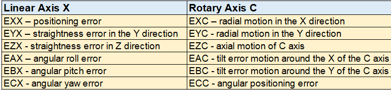
Table 1. (The error description of a linear axis)
As early as 1932, German professor Georg Schlesinger published the book “Inspection Test on Machine Tools,” which became the basis for a unified system for assessing the accuracy of machine tools.
In this book, he introduced guidelines for the use of devices and equipment for machine tool inspections.
Measurement procedures and tolerances for permitted deviations are also given. The name of Prof. Schlesinger is used to informally call the geometric accuracy tests of machine tools.
The devices and aids most commonly used to measure geometric errors in machine tools are, for example, granite rulers and cubes, dial gauges, digital inclinometers, autocollimators, or laser interferometers, which are increasingly used for measurement.
The principle of light interference as a measurement tool can be traced back to 1880 when Albert Michelson invented interferometry.
The Michelson interferometer consists of a wavelength (monochromatic light) light source, a silver-plated mirror, and two other mirrors.
Although modern interferometers are more precise, with a measurement accuracy of one part per million or higher, they still use the basic principles of Michelson interferometers.
The straightness measurement shows deflection (bent component) or misalignment in the machine guides. This may be due to wear, an accident that could damage them, or poor machine foundations that cause the axis or the entire machine to fall.
Squareness is measured by comparing the straightness of two nominally orthogonal axes.
The measurement can be arranged in different ways using different fixtures and devices.
Measuring prisms, mandrels, or granite cubes may be included in the fixture, while the equipment is between the dial indicator and the laser.
Planeness measurement is performed to check the planeness of CMM tables and machine tools, plate fields, and surfaces.
It determines whether there are any significant peaks or valleys and quantifies them.
If these errors are serious, corrective operations are required. A certain number of measuring lines are required to measure the planeness of the surface.
3.2 Positioning Accuracy
This parameter describes the accuracy and repeatability of positioning in linear and rotary numerically controlled axes.
“Determination of accuracy and repeatability of positioning in numerically controlled axes” is described in the standard ISO 230-2/6 (ISO 230-2 Test code for machine tools—Determination of accuracy and repeatability of positioning numerically controlled axes.
ISO 230-6 test code for machine tools—Determination of positioning accuracy on body and face diagonals), but very often the directive VDI/DGQ 3441 is also used.
Positioning accuracy is the most common form of measurement for laser interferometers (Figure 2).
The laser system measures linear positioning accuracy and repeatability by comparing the position displayed on the machine with the actual position measured by the laser system.
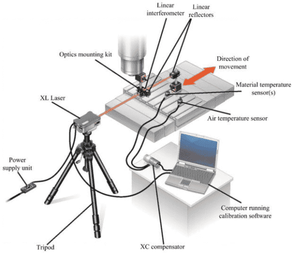
Figure 2. (Setting of measuring system for measurement of positioning accuracy)
A more advanced device for positioning accuracy measurement is the Laser Tracker, which allows for an immediate evaluation of the x, y, and z deviations.
The geometric accuracy of the machine and the accuracy of positioning can be evaluated simultaneously (Figure 3) for an already assembled and activated machine.
For this reason, the aforementioned accuracies are usually considered simultaneously.
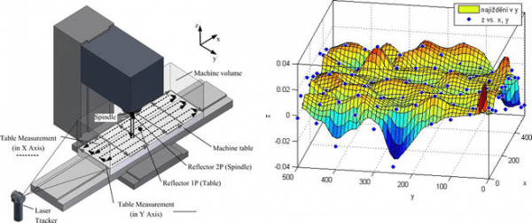
Figure 3. (Synergy when using laser trackers to evaluate geometry and positioning accuracy)
3.3 Interpolation Accuracy
In theory, if the CNC machines were perfectly accurate, then the circular path of the machine would exactly match the programmed circular path.
In practice, however, any kind of error (measuring error, straightness, clearance, reverse error, etc.) will cause the radius of the circle to deviate from the programmed circle.
If we can accurately measure the actual circular path and compare it with the programmed (nominal) path, we would get a ratio of the machine tool accuracy.
The measurement and evaluation of circular interpolation accuracy are the subjects of the ČSN ISO 230-4 standard.
The purpose of the tests is to provide a method for the evaluation of the capabilities of the contour forming of numerically controlled machine tools.
These errors are affected by geometric errors and the dynamic behavior of the machine during the feed used.
Results are visible on machined parts under ideal processing conditions if the diameter and feed are the same for both machining and interpolation testing.
3.4 Volumetric Accuracy
Advanced and highly progressive methods include the assessment of volumetric accuracy and its subsequent compensation.
The purpose of these advanced compensations is to minimize the tool center point (TCP) deviation at any point in the machine-measured workspace.
TCP volumetric deviation is defined as the sum of partial deviations in the individual axes.
The volumetric accuracy of machine tools is represented by the vector diagram of the error deviation in the working space. In the standard ISO 230-1, the concept of volumetric accuracy for a three-axis center is defined as the maximum range of relative deviations between the actual and ideal position in the X, Y, and Z directions.
And the maximum range of deviations orientation for directions of A, B, and C axes for motions in X, Y, and Z axes in the specified volume, where the deviations are the relative deviations between the tool and the workpiece on the machine tool for specified alignment of the primary and secondary axes.
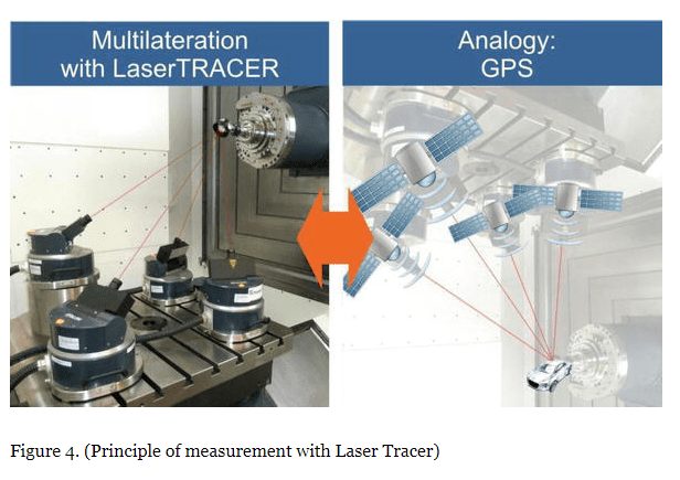
The Laser Tracer measuring device (Figure 4) is mainly used for measuring volumetric accuracy and subsequent volumetric compensation.
The principle of the Laser Tracer measurement is based on the measurement of beam lengths (HeNe laser wavelengths, 632.8 nm) and the calculation of the measured point in the workspace by the method of sequential multilateralism.
With this method, it is necessary to measure gradually from multiple locations on the machine (it is recommended to measure from at least four Laser Tracer positions).
The method is presented as an analogy to the GPS.
3.5 Working Accuracy
This is a property of a machine tool that expresses the quality and productivity of a potential workpiece production.
Working accuracy is expressed by the production of a test workpiece or a series of test workpieces.
The working accuracy of the machine is affected by the accuracy of the relative tool path.
Geometric accuracy of the machine.
Tool positioning accuracy relative to the workpiece (positioning accuracy).
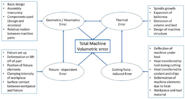
Figure 5. (Overview of the error budget in a machine tool and its influencing factors).
Resistance of the machine to elastic deformations (caused by cutting forces, workpiece weight, etc.)
Resistance of the machine to thermal expansion (“thermal stability”).
Selection of cutting conditions, etc.
An overall summary of factors affecting the accuracy of the machine tool is shown in Figure 5. The resulting error in the Cartesian coordinate system is shown by Eq. as a spatial error between the programmed and the actual TCP position.
Test workpieces to be tested for working accuracy are given, for example, by ISO 10791–7. Here, a test workpiece for 3-axis machining is designed.
Furthermore, test workpieces are aimed at continuous 5-axis machining. An example is the test workpiece defined by the directive VDI NCG 5211-1.
3.6 Production Accuracy
Production accuracy describes the production process accuracy evaluated on the workpiece.
Production accuracy is influenced by geometrical accuracy, positioning accuracy, and working accuracy, and also by the errors of machine operators (incorrectly adjusted tool, poorly clamped workpiece) and by changes in ambient conditions.
Variations in the dimensions of the test workpieces during the production process provide direct information on production accuracy.
Production accuracy is usually monitored by SPC (statistical process control).
This method has already been overcome in some production processes with 100% product control. Due to the spectrum of workpieces of medium-sized and large CNC machine tools, the SPC method can still be considered valid.
The three main influences that affect the machine tool and the production process and cause workpiece dimensional variations can be more closely assigned to:
- Production Technology 15%.
- The Working Accuracy of The Machine is 25%.
- Measurement 15%.
- Ambient conditions 20%.
- Machined part 5%.
- Machine operator 20%.
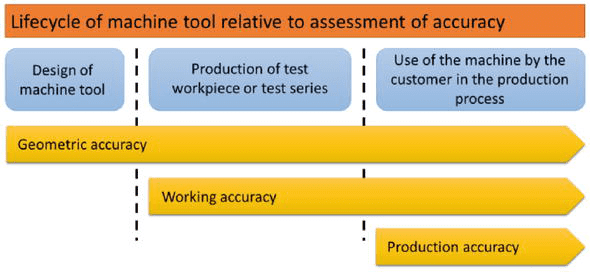
Figure 6. (Relationships between individual accuracies of a CNC machine tool throughout its life cycle).
The above-mentioned partial accuracies of the machine tool can be divided into individual parts of the life cycle (Figure 6).
Production accuracy can, therefore, be monitored at the phase of the customer’s machine use and is influenced by both the working accuracy of the machine and the long-term stability of geometric accuracy.
4 The Main Cause of Errors In Machining Accuracy
Machining accuracy refers to the degree of conformity between the actual geometric parameters (size, shape, position) of the processed parts and the ideal geometric parameters. In processing, error is inevitable, but the error must be within the allowable range.
Through error analysis, master the basic law of its change to take corresponding measures to reduce processing errors and improve processing accuracy.
Then there will be errors and there will be reasons, roughly as follows:
4.1 Spindle Rotation Error
The spindle rotation error refers to the variation of the actual rotation axis of the spindle relative to its average rotation axis at each moment.
The main reasons for the radial rotation error of the main shaft are the coaxiality error of several sections of the main shaft journal, various errors of the bearing itself, the coaxiality error between the bearings, and the deflection of the main shaft.
4.2 Guide Rail Error
The guide rail is the benchmark for determining the relative positional relationship of various machine tool components on the machine tool, and also the benchmark for machine tool movement.
The uneven wear and installation quality of the guide rail are also important factors that cause the guide rail error.
4.3 Transmission Chain Error
The transmission error of the transmission chain refers to the error of the relative movement between the transmission elements at the first and the end of the transmission chain.
The transmission error is caused by the CNC manufacturing and assembly errors of each component of the transmission chain and the wear during use.
4.4 The Geometric Error of the Tool
In the cutting process of any tool, it is inevitable to produce wear, and thus cause a change in the size and shape of the workpiece.
In the machining of CNC machine tools, the geometric accuracy of the machine tool is affected by external factors such as the external force and the heat generated by the CNC machining process.
The geometrical distortion of the CNC machined parts on the machine tool causes geometric errors.
According to research, the main reasons for the geometric error of CNC machine tools are nothing more than the following two factors: internal factors and external factors.
The internal factors that cause geometric errors of the machine tool refer to the errors themselves caused by the geometric factors of the machine, such as the level of the working surface of the machine tool, the level and straightness of the machine tool guide, and the geometric accuracy of the machine tool and fixture.
External factors mainly refer to the geometric errors caused by the external environment and thermal deformation during CNC processing.
For example, when the tool or CNC part is in the cutting process, due to thermal expansion and deformation, geometric errors will occur, which will affect the CNC machining of the machine tool. The precision and machining accuracy of the CNC machined parts.
4.5 Positioning Error
One is the error of benchmark non-coincidence. The datum used to determine the size and position of a certain surface on the CNC machining part drawing is called the design datum.
The reference used to determine the size and position of the processed surface of this CNC process on the CNC process drawing is called process reference.
When CNC machining a workpiece on a machine tool, several geometric elements on the workpiece must be selected as the positioning datum during CNC processing.
If the selected positioning datum does not coincide with the design datum, a datum misalignment error will occur.
The second is the inaccurate error of the positioning pair CNC manufacturing.
Position error refers to the deviation or degree of deviation of the actual surface, axis, or symmetry plane of the CNC processed part from its ideal position, such as perpendicularity, positioning, symmetry, etc. The position error in CNC machining usually refers to the dead zone error.
The cause of the position error is mainly due to the CNC machining error caused by the gap and elastic deformation generated during the CNC machining of the CNC machine parts, and the machining head needs to overcome the friction during CNC machining. Other factors lead to positional errors.
In the open-loop system, position accuracy is greatly affected. In the closed-loop servo system, it mainly depends on the CNC machining parts’ accuracy of the displacement detecting device and the speed amplification factor of the system, and the general influence is generally small.
Through long-term data analysis and practical operation of CNC parts processing, machine positioning has a great influence on the machining accuracy of CNC machine tools.
The CNC machining error of CNC machine tools is caused by the positioning accuracy from the structural point of view.
The feed system of the machine tool is the main link that affects positioning accuracy. The feed system of CNC machine tools is usually composed of two parts: a mechanical transmission system and an electrical control system.
The positioning accuracy is related to the mechanical transmission system in the structural design. In a closed-loop system, CNC machine tools can often prevent positional deviations in the main components of the feed system, such as ball screws, using position detection devices.
For the open-loop system, due to the many influencing factors and the complicated situation, positioning and monitoring cannot be carried out, which greatly affects the machining accuracy of the CNC machine tool.
4.6 Errors Caused by Force And Deformation of the Process System
One is the stiffness of the workpiece. In the processing system, if the rigidity of the workpiece is relatively low compared to the machine tool, cutting tool, and fixture, the deformation of the workpiece due to insufficient rigidity will have a greater impact on the machining accuracy under the action of cutting force.
The second is tool stiffness. The rigidity of the external turning tool in the normal direction of the machined surface is very large, and its deformation can be ignored.
Boring an inner hole with a small diameter, the rigidity of the toolbar is very poor, and the force and deformation of the toolbar have a great influence on the machining accuracy of the hole.
The third is the stiffness of machine tool components. Machine tool components are composed of many parts. So far there is no suitable simple calculation method for the stiffness of machine tool components.
At present, experimental methods are mainly used to determine the stiffness of CNC milling machine parts components.
4.7 Errors Caused by Thermal Deformation of the Process System
The thermal deformation of the CNC process system has a relatively large impact on the CNC machining accuracy, especially in CNC precision machining and large CNC parts processing, the machining error caused by the thermal deformation can sometimes account for 50% of the total error of the workpiece.
5 Causes and Analysis of Machining Accuracy and Machining Error
CNC machining accuracy and CNC machining error are used to evaluate the surface parameters of CNC machining parts.
Usually, machining accuracy is the application of mathematical tolerance grade to express, the smaller the numerical value of the grade, the higher the precision requirements of CNC machining parts.
Machining needs to have a smaller processing error! The CNC machining error is mainly due to a reaction with a concrete numerical value, the greater the numerical also that machining error, the greater the CNC processing and the lower the accuracy.
In the process of mechanical parts processing, regardless of whether any machining manner is likely to be one hundred percent accurate, there will always be some machining error, only machining error is smaller, the higher the quality of the processing, CNC machining parts to meet the needs of the user.
But in the actual CNC machining process, CNC machining precision of the confirmation need about the actual need, only from the point of CNC processing quality, natural CNC machining accuracy is higher, the CNC machining quality is better, but the CNC machining precision of the ascension, often require a greater economic input, increase the cost of machining.
Therefore, at the time of confirmation for CNC machining precision, it also needs to be determined according to the actual needs, so that the CNC machining can not only meet the needs of users but also maintain the economic cost of CNC processing.
5.1 Process System Error Analysis
Among the factors affecting precision CNC machining, CNC process system error is a very important point, which can be analyzed, mainly divided into two parts: Mechanical parts in the process of processing mainly needed through machine tools and tools to achieve.
And then the machine itself is also a mechanical product, there is a certain error, and this error is bound to affect the accuracy of mechanical CNC parts processing!
At the same time in the process of CNC machining, the machine tool will produce vibration, the vibration will affect the precision of CNC processing and the use of the machine tool bearings for a long time.
And there will be a certain degree of wear and tear, and there is inevitably a phenomenon, but this kind of phenomenon will influence the precision machinery processing, and reduce CNC machining accuracy in addition to this, the tool is an essential part of mechanical processing.
There will be differences between different tools, which will affect the final CNC machining accuracy, but this factor on the accuracy of machining has a small impact and is usually ignored.
5.2 Position Error Analysis
In the CNC machining process, you first need to fix parts, then according to the related parameters for processing in the process of all mechanical parts the location is relatively fixed, but the location of the setting needs to be the initial positioning.
There may be some errors in positioning, and ideally, the location produces certain deviations, the CNC machining process behind nature will also be affected, thus affecting the quality of precision CNC machining.
When the positioning error is greater, the greater the impact on mechanical precision CNC machining, making the final CNC machining parts of the effect worse therefore, mechanical CNC processing should strengthen the control of positioning error, as far as possible to reduce the error in this respect.
5.3 Force Deformation Error Analysis
Gravity is generated during CNC machining and cutting force! Transmission force and other forces, when these forces act on CNC machined parts and machine tools, will make CNC machined parts and machine tool CNC parts appear to a certain degree of deformation and then affect the mechanical precision processing, the following launch a specific analysis.
5.3.1 Influence of Machined Parts Stiffness
CNC Machined parts Due to the influence of the material, the stiffness between different CNC parts is also different, when the cutting tool for its cutting, will produce a cutting force on the CNC parts.
This cutting force in different stiffness of the CNC machined parts of the deformation effect is not the same, thus affecting the mechanical precision CNC processing.
This is also the precision CNC processing that should focus on the analysis and consideration of the place.
5.3.2 Impact of Machine Tool Component Stiffness
CNC machining on the machine tool, and machine work, in the long run, the machine tool components may appear to some extent, the deformation of the machine CNC parts and the difference between the ideal and affect the CNC machining precision of the deformation of the machine tool.
CNC machined parts and there is a direct link between the stiffness of machine components and machine parts stiffness has become one of the influence factors of mechanical precision CNC machining.
Essentially causes the mechanical CNC processing force deformation error has two main reasons: first, the cutting force in the process of CNC cutting is caused by changes in the whole CNC machining system, resulting in the emergence of CNC machining error, for this situation is usually because of the CNC processing allowance change.
Unequal processing of workpiece material is caused by; Second, the need to be in the process of machining parts clamping, the fixture can produce strong force for CNC processing parts, which can cause deformation of CNC machining parts.
And causes the occurrence of an error, for this kind of situation lies in the process of the workpiece clamping position being inaccurate and causing the deformation of CNC machined parts produced bigger, making the deformation error increase, affecting the CNC machining accuracy.
5.4 Thermal Deformation Causes Machining Errors
CNC Machining error caused by thermal deformation is one of the most important factors in CNC machining accuracy, and its influence may be neglected in ordinary machining.
However in the CNC processing of precision workpieces and large workpieces, its influence is very obvious, and sometimes the CNC processing error caused by thermal deformation will account for more than half of the total error of the processed workpiece.
And this thermal deformation error is unavoidable, in CNC machining parts! Machine tool! Cutting tools in the process of CNC processing will generate greater heat, which may cause a thermal change in shape, and affect the CNC machining accuracy of should be fully considered in the process of CNC production and CNC processing.
Therefore, the impact of actively doing a good job in the heat makes the unit time equal to the heat coming from the heat and maintain, maintains the state of heat balance, to reduce the ill effects of thermal deformation of CNC machining parts.
5.5 Error Caused by Internal Stress
For every mechanical CNC part, the stress is independent of external stress and belongs to the inner power of CNC machined parts, but this kind of inner strength can also cause deformation of mechanical CNC parts, and increase the CNC machining error when machining CNC parts itself contains high internal stress, high internal could in an unstable state.
They will move to the low energy, and in the process of this transfer will produce a certain degree of deformation, so the CNC machining accuracy is greatly affected.
6 Ways to Improve the Machining Accuracy of CNC Machine Tools
In the CNC machining process of CNC machine tools, the accuracy of the CNC parts processed directly affects the quality of the products. Some mechanical CNC parts and precision equipment parts require high CNC machining accuracy. Improving the machining accuracy of CNC machine tools is the key to solving this problem.
Through extensive research and analysis, it is concluded that there are several ways to improve the CNC machining accuracy of CNC machine tools:
6.1 Improve Machining Accuracy by Controlling the Original Error of CNC Machine Tools
In the CNC machining process of CNC machine tools, the error itself is inevitable, and there is an inevitable error between the CNC machined parts and the CNC machine tools.
This certain error is called the original error.
Therefore, to improve the CNC machining accuracy of CNC machine tools, controlling the original error of CNC machine tools is one of the important countermeasures.
Analyze the possibility of the original error of the system, and take corresponding improvement measures according to the cause of the error and the type of error. In the CNC machining process, the position accuracy and geometric accuracy of the CNC machine tool have an important influence on the machining accuracy of the CNC machined parts.
Position control and geometric CNC precision control are used to reduce the influence of position error and geometric error on the CNC parts.
At the same time, for the deformation error generated during the CNC processing, air-cooling, water-cooling, and other methods should be used to control the thermal deformation during the CNC machining process, and the CNC machining accuracy caused by the thermal deformation error is reduced.
At the same time, for the position error, it is necessary to choose a tool suitable for the material of the CNC machined part reasonably to avoid the deformation of the tool and choose a reasonable fixture according to the shape of the CNC part to be processed.
If necessary, specially design fixtures for the shape and size of the CNC machining parts to avoid them.
6.2 Reasonable Design of the Core Components of the Machine Tool to Avoid Positioning Errors
The CNC positioning accuracy of the machine tool has an important influence on the accuracy of the components, and the core components that affect the CNC positioning accuracy of the machine such as the straightness and level of the feed system, guide rails, and work surfaces.
When designing a CNC machine tool, it is necessary to select the core components reasonably.
For example, when selecting the ball screw that is widely used in machine tools, the accuracy of the ball screw should be fully considered.
The ball screw technology that is more mature should be selected and installed. The support of the ball screw can not be ignored.
The support of the ball screw is closely related to the transmission accuracy of the system.
The support of the ball screw is mainly determined by the axial load and the rotation speed, which has an important influence on the CNC machining accuracy of the CNC lathe. Accuracy fixing and support.
In the design process, the bearing capacity of the ball screw should be strictly checked.
The drag chain, as part of the machine’s outer protection, is now indispensable for machine tools. Due to its chain structure, certain vibrations will also occur following the movement of the tool holder.
This vibration will be transmitted directly to the tool, which will have a certain impact on the CNC machining accuracy.
6.3 Improve the Machining Accuracy of CNC Machine Tools Through Real-time Monitoring Technology
With the continuous improvement of numerical control technology, the CNC machine tool is processed in real-time, the error link in the CNC machining process is adjusted in time, and the error data of each link in the CNC machining process is collected and fed back to the control terminal.
The error data adopts the corresponding error compensation mechanism to perform timely error compensation, which can effectively improve the CNC machining accuracy of the CNC machining parts.
7 Measurements to Calculate CNC Milling’s Accuracy
Three different measurement methods determine the overall accuracy of a milled part: positioning accuracy, precision or repeatability, and tolerance.
7.1 Positioning Accuracy of the Mill
The positional accuracy is equal to the difference between the specified distance between points on a part and the actual measured distance of those points once they have been milled. For a CNC milling machine, the accuracy depends on how well it can follow its programmed paths.
The CNC machining workshop determines the accuracy of the rolling mill through multiple measurements and calculating the statistical average of the deviations.
7.2 Repeatable Precision
The CNC machining shop defines the precision of the rolling mill by precisely repeating the same commands, or G-code, to deliver the same results one after another.
Similar to accuracy, when a CNC milling machine is required to cut a path, the factory can calculate the accuracy of the CNC milling machine through multiple measurements.
The measurement of accuracy lies in the repeatability of cutting the same precise path and finally producing accurate repeating CNC machined parts.
7.3 Tolerance of the Finished Part
CNC Machinists and engineers use the term tolerance when referring to the allowable deviation of a CNC milling machine from a measured set value. CNC programmers and machinists program the rolling mill to manufacture parts within the tolerances required by the customer.
When cutting materials and producing CNC parts, the rolling mill should stay within these set tolerances.
The goal of a CNC milling machine is to keep it within a specified tolerance range by repeatedly maintaining a high CNC positioning accuracy.
For example, imagine shooting an arrow at a target. The distance between the arrow and the bull’s eye is the key to measuring accuracy.
The distance between the arrows is equal to the repeatable accuracy. When processing a batch of CNC machining parts, the repeatability is not accurate and will not produce any usable results because the parts will all be out of tolerance equally.
Or, accuracy without repeatability will result in only one or two parts being available. The combination of precision and repeatability will produce a whole batch of qualified CNC products.
The machine shop uses this precision to ensure the quality of the CNC machining parts.
8 Conclusion
To sum up, the CNC machining process is more complicated and needs to take many factors into account, mechanical processing needs various aspects to consider the influencing factors, and then make a scientific and reasonable processing scheme or processing steps, such as the ability can effectively reduce the error that exists in the process, thus effectively enhance machining accuracy.
The quality of machining becomes higher, in line with the needs of the more machined workpiece.
Thank you for reading.
We hope this information will help you. For more information, don’t hesitate to contact us by the below box to get more information from YIJIN Solution.