
Every manufactured part carries a surface finish specification, and that specification translates directly into production cost. Whether the drawing calls out Ra 0.8 µm, N6, or a general surface finish symbol, the value you specify determines cycle time, tooling selection, and whether a secondary finishing operation is required.
This article covers what surface finish means, how to read the roughness chart, what each Ra level costs to achieve, and how to call out only the finish your application requires.
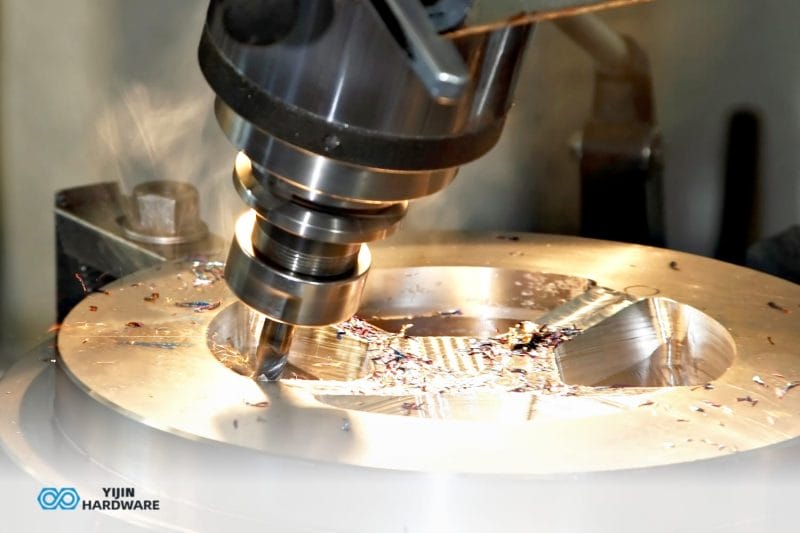
What is Machining Finish?
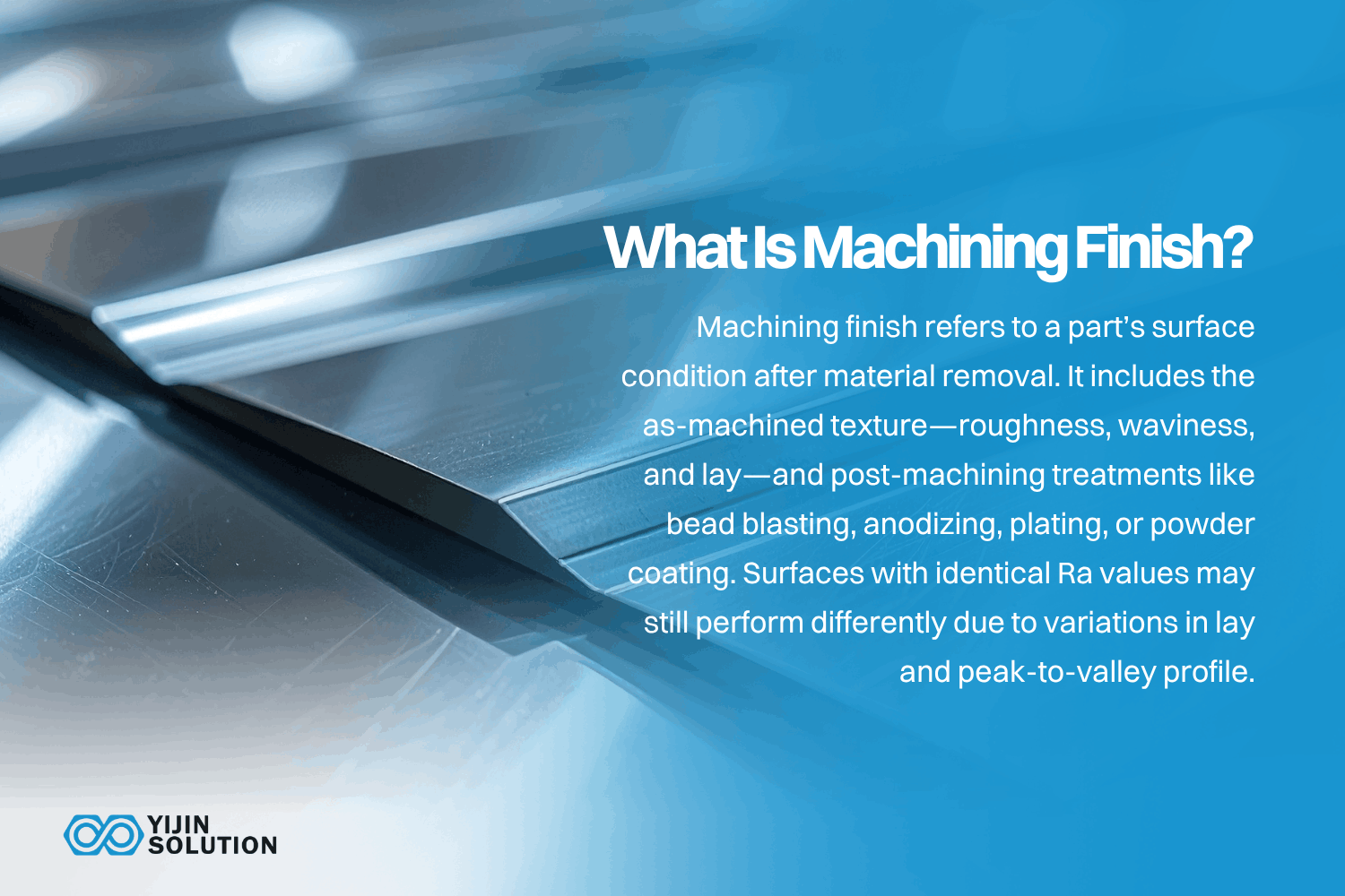
Machining finish is the surface condition left on a part after a material removal operation. The term covers two distinct things: the as-machined surface texture produced by the cutting process, and the post-machining surface treatments applied afterward.
As-machined surface texture has three components. Roughness is the fine-scale irregularity left by the cutting tool, measured in micrometers. Waviness is the larger-scale undulation caused by vibration, deflection, or thermal distortion during the cut. Lay is the directional pattern the operation leaves behind. Turning produces circular lay. Milling produces parallel or perpendicular lay depending on the toolpath.
Post-machining treatments modify the as-machined surface for functional or cosmetic reasons. Bead blasting, anodizing, plating, and powder coating all fall into this category. Full coverage of these processes appears later in this article.
Two surfaces with the same Ra value can behave differently in service if their lay directions or peak-to-valley distributions differ. Ra alone does not describe the full surface condition.
Surface Roughness Chart: Ra, Rz, and N Grade Values
The chart below maps N grade designations to Ra values, typical manufacturing processes, and common applications. Ra is the most widely specified parameter, but it averages out surface extremes. For surfaces in which peaks and valleys matter, Rz or Rt may be the better control parameter.
| N Grade | Ra (µm) | Ra (µin) | Typical Process | Rz (approx.) | Aplicaciones comunes |
|---|---|---|---|---|---|
| N1 | 0.025 | 1 | Superfinishing | 0.1 µm | Gauge blocks, optical components |
| N2 | 0.05 | 2 | Lapping | 0.2 µm | Precision seals, bearing races |
| N3 | 0.1 | 4 | Fine honing/lapping | 0.5 µm | Hydraulic cylinder bores |
| N4 | 0.2 | 8 | Grinding/polishing | 1.0 µm | Sealing surfaces, medical implants |
| N5 | 0.4 | 16 | Fine turning/milling | 2.0 µm | Sliding surfaces, O-ring grooves |
| N6 | 0.8 | 32 | Precision CNC turning | 4.0 µm | Bearing journals, precision fits |
| N7 | 1.6 | 63 | Standard CNC turning | 8.0 µm | General precision machining |
| N8 | 3.2 | 125 | Standard CNC milling | 16 µm | Default as-machined finish |
| N9 | 6.3 | 250 | Rough milling/turning | 25 µm | Non-critical structural faces |
| N10 | 12.5 | 500 | Rough machining | 50 µm | Hidden faces, rough blanks |
Source: N Grade designations and Ra/Rz parameter conventions per ISO 22476 y ISO 21920.
When to use Ra vs Rz vs Rt
Ra is the arithmetic average of surface height deviations from the mean line. It is the default roughness parameter on most drawings and purchase orders. The limitation: Ra smooths out extremes. A surface with a few deep scratches and an otherwise smooth profile can report the same Ra as a uniformly rough surface.
Rz captures what Ra misses. It averages the five highest peaks against the five deepest valleys within the sampling length. For sealing surfaces and coating adhesion, Rz is a better predictor of functional performance than Ra. Specify Rz alongside Ra on any surface that involves leakage risk or coating failure.
Rt is the total height of the roughness profile, peak to valley, across the entire measurement. It catches the single worst-case defect. Use Rt as a QC screening parameter when even one deep scratch or tool mark is unacceptable. ASME B46.1 y ISO 21920 define all three parameters and their measurement conventions.
How do you read surface finish symbols on engineering drawings?
Surface finish symbols on engineering drawings follow ISO 21920 o ASME Y14.36M conventions. The basic symbol is a check-mark shape. A circle at the base means material removal is not permitted. A bar across the top means material removal is required.
The Ra value sits above the check mark. Lay direction symbols appear alongside: parallel lines for parallel lay, crossed lines for multidirectional, a “C” for circular lay from turning, and an “R” for radial. When the application is sensitive to surface direction, specifying lay is as important as specifying Ra.
What Determines Machining Finish?
As-machined surface finish is the result of five controllable variables. Each one affects the roughness your shop delivers, and each one carries a cost trade-off.
Feed rate and stepover
Feed rate has the single largest effect on surface roughness in most CNC operations. In turning, surface roughness is proportional to the square of the feed divided by the nose radius. Doubling the feed roughly quadruples the theoretical Ra. In milling, stepover controls cusp height between adjacent passes. Reducing stepover improves finish at the cost of longer cycle time.
Tool geometry and condition
Nose radius, rake angle, and edge condition all affect finish quality. A larger nose radius produces a smoother surface in turning. A worn or chipped insert edge will not hold a consistent Ra regardless of parameter settings, which is why tool condition often explains a finish problem that the cutting numbers cannot.
Cutting speed
Higher surface speed generally improves finish, up to a point. In aluminum, speeds above 300 m/min produce noticeably better surface quality. In stainless steel, the relationship is less straightforward because work hardening and built-up edge formation become factors at certain speed ranges.
Propiedades de los materiales
Aluminum 6061 finishes cleanly at high speeds with minimal effort. Gummy alloys like 304 Stainless Steel or pure copper are harder to finish because they tend to smear rather than shear. Hard materials like D2 tool steel can produce excellent finish quality but accelerate tool wear. That limits how long the process holds a given Ra.
Machine rigidity and workholding
Vibration during the cut degrades surface finish more than most parameter choices can recover. A rigid machine with solid workholding produces better finish than optimized cutting parameters on a worn spindle with compliant fixturing. Chatter shows up as evenly spaced marks on the surface, and it is measurable. Production CNC systems with robust workholding tend to hold a tighter finish than open-fixture prototype setups.
Standard Machining Finishes and What They Cost
Each finish tier carries a distinct cost profile. Understanding the cost jumps helps engineers and procurement teams match finish specs to what the part actually needs.
Ra 3.2 µm: the default as-machined finish
Ra 3.2 µm is what most CNC shops deliver when no surface finish is specified on the drawing. Tool marks are visible under close inspection, but the surface is functional for non-critical faces, structural mounting surfaces, and internal features. No additional machining time or tooling changes are needed beyond the standard operation. This is the cost baseline.
Ra 1.6 µm: general precision machining
Achieving Ra 1.6 µm requires a finishing pass with reduced feed, a sharp insert, and higher spindle speed. Expect roughly 10% to 20% additional cycle time on most features. This finish suits bearing journals, mating surfaces, and general precision fits that require parts to assemble without interference.
Ra 0.8 µm: precision surfaces
Ra 0.8 µm demands optimized parameters, sharp tooling, and a stable setup with minimal vibration. Some geometries need grinding or honing to hit this value reliably across the entire surface. Cost increases meaningfully at this level. Specify Ra 0.8 µm only for functional requirements: sealing faces, sliding interfaces, and precision bores.
Ra 0.4 µm and below: high-precision and optical
Below Ra 0.4 µm, you are generally into grinding, honing, lapping, or polishing territory. Turning or milling alone will rarely hold these values across a full surface, so a secondary operation usually does the work. The cost premium is significant, and the operations are time-intensive. Medical implants, optical lens mounts, semiconductor fixtures, and high-pressure sealing surfaces are the typical applications. Specify this range only with clear functional justification.
Types of Surface Finishes in Machining
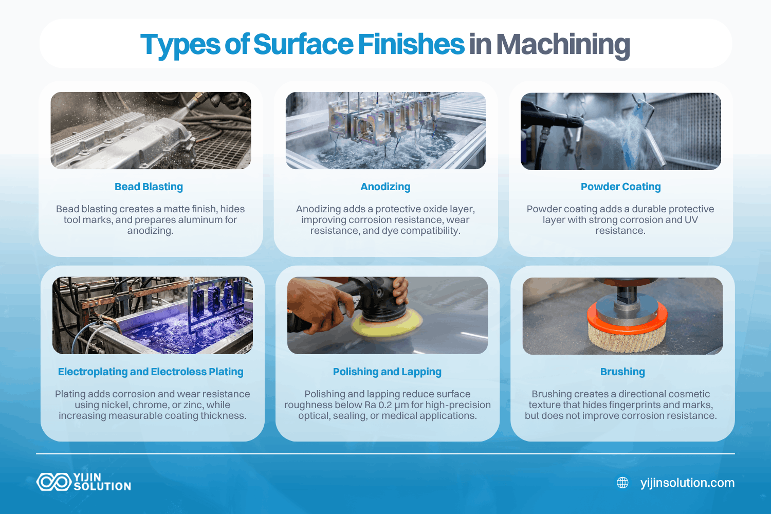
Post-machining finishing modifies the as-machined surface for cosmetic, functional, or protective reasons. The processes below cover the most common options for machined and fabricated parts.
Bead blasting
Bead blasting creates a uniform satin or matte texture that hides tool marks. Dimensional change is negligible. Glass-bead blasting typically produces Ra 1 to 3 µm. The process is commonly used as a pre-anodizing surface preparation step on aluminum parts. Learn more about bead blasting.
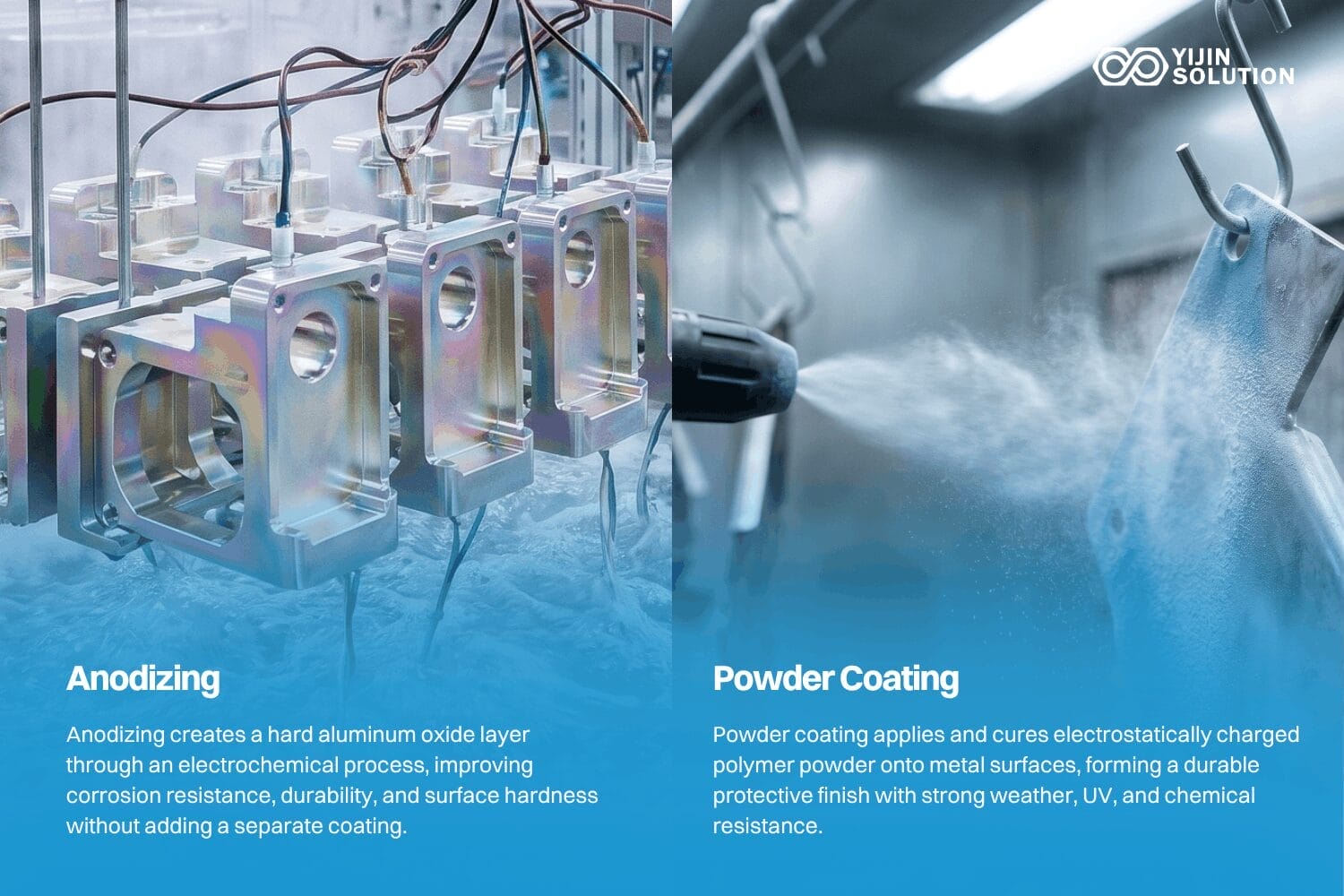
Anodizado
Anodizing builds an electrochemical oxide layer on aluminum. Type II provides corrosion resistance and accepts color dye, adding roughly 0.005 to 0.025 mm per side. Type III hardcoat delivers wear resistance and can add up to 0.075 mm per side depending on coating thickness. Anodizing slightly increases Ra compared to the pre-anodized surface.
Recubrimiento en polvo
Powder coating applies dry polymer powder electrostatically, then cures it with heat. It adds 0.05 to 0.1 mm thickness per side and hides surface imperfections effectively. Corrosion resistance and UV resistance are both strong. Powder coating is not suitable for tight-tolerance mating surfaces unless those areas are masked before application.
Electroplating and electroless plating
Nickel, chrome, and zinc plating are the most common options. Electroless nickel plating produces a uniform coating with precise thickness control, making it well-suited for corrosion and wear applications. Chrome plating can improve surface roughness by filling micro-valleys. All plating processes add measurable thickness that must be accounted for in the tolerance stack.
Polishing and lapping
Mechanical polishing and lapping remove material progressively to achieve Ra below 0.2 µm. Both processes are labor-intensive and expensive. Specify them only for a functional need: optical surfaces, fluid seals under high pressure, or medical implant contact faces.
Cepillado
Brushing produces a directional texture using abrasive media. The result is a cosmetic finish that hides fingerprints and minor handling marks. It is common on consumer electronics enclosures and architectural metalwork. Brushing does not improve corrosion resistance on its own.
For a full range of post-machining finishing options, visit our surface finishing services.
How to Specify Machining Finish Without Over-Engineering Cost
Over-specifying surface finish is one of the biggest cost drivers that engineers control without realizing it. Every Ra callout on a drawing adds machining time, tooling wear, and inspection cost. The guidance below helps match specifications to functional requirements.
Specify Ra only where function requires it
The default: do not specify finish on non-critical surfaces. Most shops deliver Ra 3.2 µm or better as their standard output. Adding Ra callouts to every surface on a drawing increases machining time and inspection scope. Specify roughness only on functional interfaces: sealing faces, bearing journals, sliding surfaces, mating interfaces, and cosmetic faces visible to the end user.
How do you match the Ra value to the application?
Sealing surfaces require Ra 0.4 to 0.8 µm, depending on seal type and operating pressure. Sliding interfaces call for Ra 0.4 to 1.6 µm. General mating surfaces work well at Ra 1.6 µm. Cosmetic surfaces typically need Ra 0.8 to 1.6 µm, or a bead blast finish. Structural non-contact surfaces do not require a roughness callout.
Should you specify Rz alongside Ra for critical surfaces?
For sealing surfaces, Ra alone can miss extreme peaks that cause leakage. Specifying Rz as a secondary control parameter gives the manufacturer a tighter band. Example: “Ra 0.8 µm max, Rz 4 µm max.” This dual callout catches surfaces that pass Ra but have isolated high peaks.
Factor in post-processing when specifying finish
If the part will be bead blasted or anodized after machining, the as-machined finish does not need to hit the final cosmetic target. Bead blasting overrides the machined texture. Conversely, if anodizing will slightly increase Ra, the pre-anodizing machined finish must be tighter than the final specification to account for the change.
Getting the Right Finish for Your Parts
A surface finish is only as good as its fit to the part’s function, and the cleanest specifications come from deciding what each surface actually needs before machining begins. Yijin Solution plans finish requirements alongside the manufacturing process, so the as-machined target and any post-processing are set together rather than after the fact.
Upload your design with your target surface finish and our engineering team will return a quote and DFM feedback within one to two business days.
Machining Finish FAQs
What is the standard surface finish for CNC machined parts?
The default as-machined finish for most CNC operations is Ra 3.2 µm, equivalent to 125 µin or N8 on the ISO roughness grade scale. A drawing with no roughness callout is read as accepting this standard output, so leaving a non-critical surface unspecified is a deliberate cost choice, not an omission. Add a tighter callout only when the surface has a function that depends on it.
What Ra value do I need for a sealing surface?
Sealing surfaces typically require Ra 0.4 to 0.8 µm. The reason to get this band right is that the failure runs in both directions: too rough leaves a leak path along the tool marks, while too smooth can starve an elastomer seal of the micro-texture it needs to seat. Because Ra averages out isolated peaks, a single high point can still breach a seal that passes its Ra check, which is why Rz is worth adding as a secondary limit on pressure-critical seals.
Does surface finish affect part cost?
Yes, directly. Tighter surface finish requires slower feed rates, additional finishing passes, sharper tooling, and more inspection time. Moving from Ra 3.2 µm to Ra 0.8 µm can add 15% to 30% to cycle time on a given feature. Moving below Ra 0.4 µm usually requires secondary operations like grinding or polishing. Specify tighter finish only where function demands it.
Does the machining direction (lay) matter for surface finish callouts?
Yes, lay is the dominant surface pattern left by the cutting tool. Turning produces circular lay. Milling produces parallel or perpendicular lay depending on the toolpath direction. For sliding interfaces or seal grooves, lay direction can be as important as the Ra value itself. ISO 22476 defines lay symbols for drawing callouts: parallel, perpendicular, multidirectional, circular, and radial. Specify lay when the application is sensitive to surface direction.
How is surface finish measured on a finished part?
Surface finish is most commonly measured with a contact profilometer that drags a diamond stylus across the surface to record height variations. Non-contact methods include optical profilometry and white-light interferometry, used for delicate or polished surfaces. The measurement length and cutoff filter affect the reported Ra value, so the inspection standard should be specified alongside the Ra callout on the drawing.
Volver arriba: Machining Finish: Surface Roughness, Finishing Methods, and How to Specify the Right Finish for Your Parts