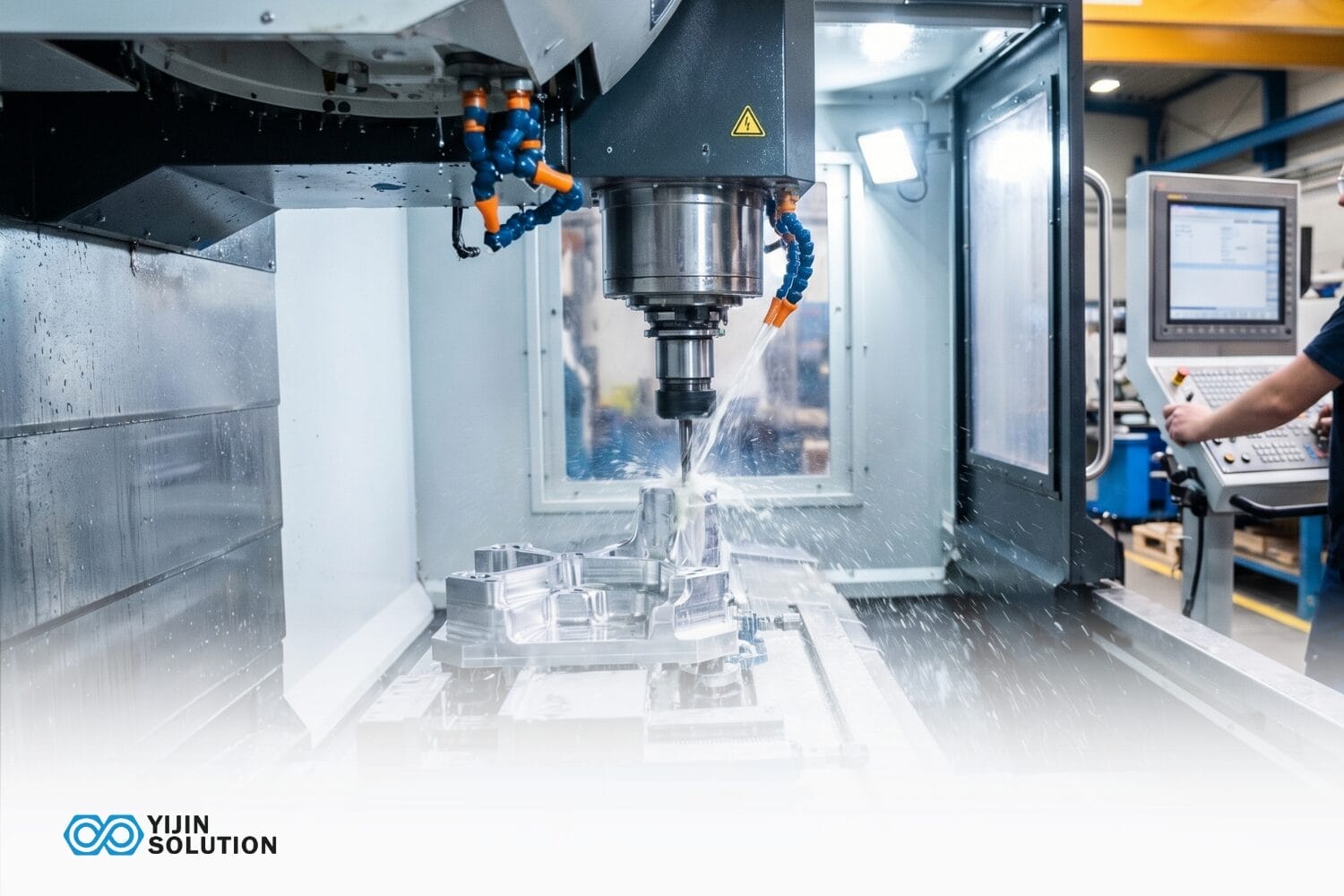

CNC machine programming software links a part design to physical machined geometry. Without it, a CNC machine has no instructions to run. That software layer determines cut accuracy, cycle efficiency, and whether the finished dimensions match the design.
CNC machine programming software covers three distinct tool types: CNC CAD tools that create the geometry, CAM systems that translate geometry into cutting instructions, and CNC control software that drives the machine’s axes in real time. Each handles a different stage of the workflow, and the quality of decisions made at each stage shapes surface finish, dimensional accuracy, and cycle time as much as the machine itself does.
Qualität CNC-Bearbeitungsdienstleistungen run on a fully integrated software-to-machine workflow from DFM-reviewed CAD files through post-processed G-code across multiple CNC centers. The guide explains how these software types work, where they fit in the machining process, and what to look for when evaluating a supplier’s software capability.
What is CNC Machine Programming Software?
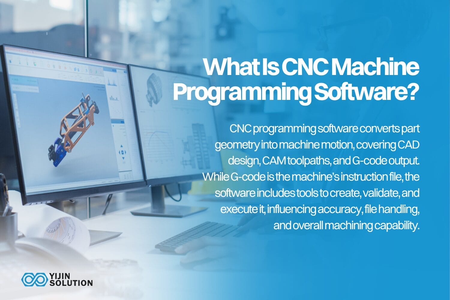
CNC machine programming software is the collective layer of digital tools that translates part geometry into machine motion. It covers the full production chain from CNC CAD geometry creation, through CAM toolpath generation and G-code output.
The term CNC computer program is sometimes used to describe the G-code file. This is the instruction set a controller reads line by line. However, CNC machine programming software is the broader category that includes the platforms that generate, validate, and execute those files.
Understanding the distinction matters when evaluating a supplier’s capability, because the software environment shapes file handling, geometry accuracy, and programming depth, not just the machine hardware running the code.
What does CNC Machine Programming Software Actually do?
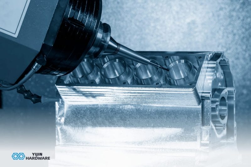
When a skilled machinist receives a part drawing, the decisions start immediately. They decide which tools to use, in what sequence, at what speeds, and how deep to cut on each pass. They plan where to hold the part so nothing moves under the cutting force.
CNC machine programming software encodes all of these decisions. It turns a geometry file into a precise set of machine instructions, automatically, at a scale and consistency that no manual process can match.
A CAD model isn’t the only component behind every machined part. Between the design file and the finished part sits an entire layer of digital engineering: geometry validation, toolpath strategy selection, and feed and speed calculation.
The quality of those decisions determines the outcome, independent of the machine hardware. Two shops running identical equipment can produce different results when their software environments, toolpath strategies, or post-processor configurations differ. Surface finish, dimensional accuracy, and cycle time are all functions of software quality.
What are the Main Types of CNC Machine Programming Software?
Three distinct software categories handle the different stages of the CNC machining workflow. Each one has a defined function and user. The table below maps them at a glance.
| Software Type | Primäre Funktion | Typical User |
|---|---|---|
| CNC CAD Software | Part geometry creation – design stage | Design engineer |
| CAM-Software | Toolpath generation + G-code output – programming stage | CNC programmer |
| CNC Control Software | Machine interface that interprets G-code and drives axes – machine operation stage | Machine operator / setup engineer |
Many machining workflows use all three types in sequence. Some integrated platforms combine CAD and CAM in a single environment, compressing the first two stages into one.
Fusion 360 is the most widely used example of this configuration. It runs CAD and CAM in the same file environment, so geometry changes update associated toolpaths automatically without a file export and re-import cycle. For job shops and in-house engineering teams working from their own designs, that tight integration reduces programming time and eliminates a common source of translation errors.
Production shops handling complex multi-axis work more often run dedicated CAD software paired with a standalone CAM package. The choice of architecture affects how files are handled between stages, and whether geometry data survives each handoff accurately enough to hold your tolerances.
CNC CAD software
CNC CAD software creates the 3D part geometry that defines every feature a machinist will cut. File quality at this stage determines downstream machining accuracy.
Poorly constrained geometry introduces tolerance errors before a single toolpath is generated. Those errors can propagate through the entire workflow and produce out-of-tolerance parts.
CNC CAD software creates the part geometry that defines every feature a machinist will cut. Common platforms in production environments include Fusion 360, SolidWorks, AutoCAD, and Onshape.
A well-defined CAD model carries full feature constraint, correct tolerances, and geometry that imports cleanly into a CAM environment without repair.
CAM software
CAM software takes the validated CAD model and converts it into toolpaths. The programmer defines which tools to use, the cutting strategy, feed rates, spindle speeds, and the depth of each pass. The CAM platform then runs a post-processor, translating the generic toolpath into G-code syntax specific to the target machine controller.
Post-processor matching is a critical detail here. A Fanuc post-processor and a Heidenhain post-processor produce different G-code syntax for the same toolpath. The most capable CAM platforms include validated post-processors for Fanuc, Siemens SINUMERIK, and Heidenhain controllers out of the box. That means less custom configuration work and more predictable G-code output for the machines your supplier actually runs.
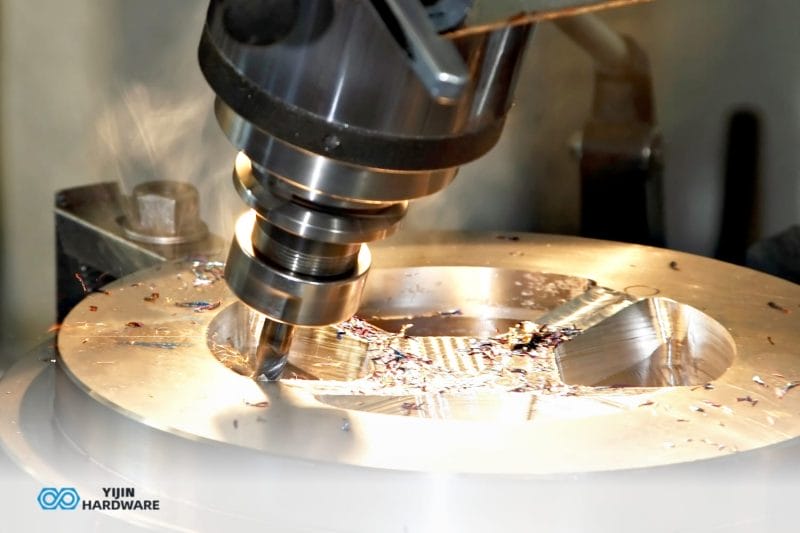
CAM strategy quality drives surface finish and cycle time more than any other programming variable. Adaptive clearing strategies reduce tool load and extend tool life on difficult materials. Finishing pass sequencing determines whether a surface meets Ra specifications as-machined or requires additional hand finishing.
CNC control software
CNC control software is the interface between the G-code program and the machine’s physical motion axes. It reads each line of code, commands axis movement, controls spindle speed and direction, triggers tool changes, and monitors machine state throughout the cutting cycle.
On production CNC machines, proprietary controller firmware handles this function: Fanuc, Siemens SINUMERIK, and Heidenhain are the dominant platforms in manufacturing environments. PC-based standalone control software serves a different market entirely, appearing mainly on converted hobby machines and custom-built equipment.
How does CNC Programming Software Fit Into the Machining Workflow?
From design file to finished part, every CNC machining job moves through a defined software-driven sequence. Each stage has a defined input, a defined tool type, and a defined output. The table below maps the standard workflow.
| Schritt | Bühne | Software Used | Output |
|---|---|---|---|
| 1 | Teil Design | CNC CAD software | 3D model / 2D drawing |
| 2 | DFM Review | CAD + DFM analysis tools | Revised geometry, tolerance callouts |
| 3 | Toolpath Programming | CAM software | Toolpath simulation file |
| 4 | Nachbearbeitung | CAM post-processor module | Machine-specific G-code file |
| 5 | Program Loading & Setup | CNC control software | Machine ready state |
| 6 | Machining & In-Process Inspection | CNC control software + probing systems | Finished part |
Platforms such as Fusion 360 compress steps 1 through 4 into a single environment. When CAD and CAM operate on the same file, changes to part geometry propagate automatically to the toolpath setup. This eliminates the file import/export cycle that introduces translation errors in separate-platform workflows.
For suppliers working directly from customer-supplied CAD files, the post-processing and verification steps remain separate regardless of the CAD/CAM architecture.
Integrated CAD/CAM vs. Standalone Software: What’s the Difference?
If you’re sending CAD files to a machining supplier, the relevant question is whether their software environment handles your files cleanly and translates your geometry accurately into machine instructions. Integrated versus standalone CAM architecture directly shapes that answer.
| Attribut | Integrated CAD/CAM | Standalone CAM |
|---|---|---|
| Design-to-toolpath workflow | Single environment: design and programming linked | Import/export required between applications |
| Geometry translation risk | Lower: no file conversion between stages | Higher: STEP/IGES conversion can introduce tolerance errors |
| Kosten | Often single subscription license | May require two separate licenses |
| Am besten für | Suppliers designing and machining in-house from the same files | Production environments receiving external CAD from customers |
| Beispiele | Fusion 360, SolidCAM, SolidWorks CAM | Mastercam, Hypermill, BobCAD |
When a supplier’s CAM environment accepts your native file format directly, the geometry translation step is eliminated. That eliminates a class of tolerance errors that can appear when surface data moves between software environments. Integrated platforms like Fusion 360 are well-suited for suppliers doing in-house design and machining from the same files.
Large production environments handling complex multi-axis work often use dedicated CAD paired with a standalone CAM package such as Mastercam or Hypermill.
The reason is that in these environments, post-processor library depth and controller compatibility is a critical evaluation criteria. A supplier running Hypermill with a validated Fanuc post-processor for your machine type will produce more consistent results than one adapting a generic post-processor.
What to Look for When Evaluating a CNC Machining Partner’s Software Capability
Software capability is a direct indicator of how accurately a supplier can handle your parts. The criteria below address what to ask and what to look for, from the perspective of an engineer or procurement team assessing whether a partner’s software environment can handle your parts accurately.
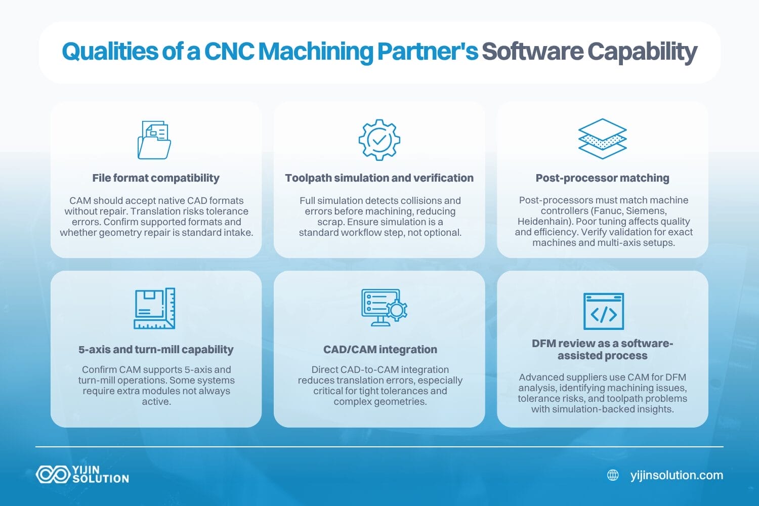
File format compatibility
A supplier’s CAM environment should accept your native CAD format without requiring geometry repair. File format translation introduces tolerance deviations before a single toolpath is generated. Ask which formats they accept natively, and whether geometry repair is a standard step in their intake process.
Toolpath simulation and verification
A supplier using CAM software with full machine simulation catches toolpath collisions and rapid-move errors before the machine runs. This directly reduces scrapped parts and avoids costly re-machining cycles. Request evidence of simulation as a standard step in their programming workflow, not an optional check.
Post-processor matching
The CAM post-processor must be configured for the specific machine controller the supplier runs. The dominant production controllers are Fanuc, Siemens SINUMERIK, and Heidenhain. A generic or poorly tuned post generates code that may run but won’t be optimized for surface quality or cycle time on that machine.
Ask which controllers are in the shop and whether the post-processors have been validated for those specific controller versions. For multi-axis or turn-mill work, also ask whether the post has been tested on the exact machine configuration your part requires, since a post validated for 3-axis Fanuc may not perform correctly on a 5-axis Fanuc setup.
5-axis and turn-mill capability
If your part requires 5-axis contouring or combined turning and milling operations, verify that the supplier’s CAM software includes the correct modules for those operation types. Not all CAM platforms handle multi-axis contouring or turn-mill natively. Some require separately licensed modules, and not every supplier has them active.
CAD/CAM-Integration
A supplier whose CAM environment works directly from the same file format you use reduces geometry translation risk at file handoff. This matters most when parts carry tight tolerances on complex surfaces, where even small translation errors can push features outside specification.
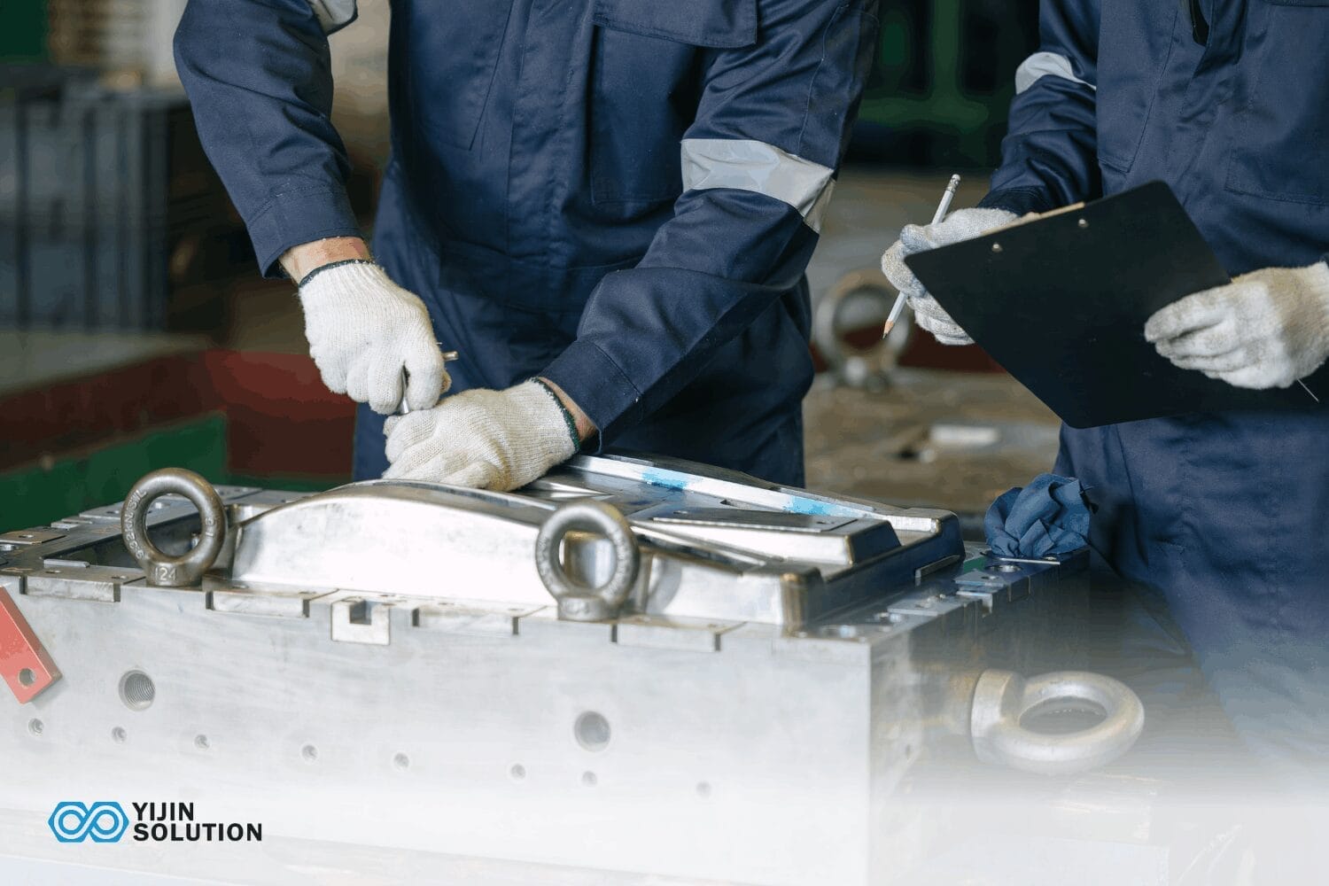
DFM review as a software-assisted process
The most capable suppliers use their CAM environment as part of design for manufacturability analysis. They identify features that are difficult to machine, tolerance callouts that exceed machine capability, or toolpath strategies that would cause surface finish problems. A free DFM review with real CAM simulation support is meaningfully different from a visual review of a drawing.
CNC Machine Programming Software vs. G-Code: What’s the Relationship?
CAM software produces the G-code file. G-code is the output language that CNC machines read. It is a text-based instruction set specifying axis positions, feed rates, spindle speeds, and tool changes. The machine controller executes G-codes line by line. CNC machine programming software generates and interprets that language.
Manual G-code programming is still necessary for simple programs like single-operation turning and basic drilling cycles on straightforward geometry. For anything more complex, CAM software handles the generation far more reliably and quickly.
A single 5-axis toolpath for a complex aerospace component can contain over 50,000 lines of G-code. Writing or verifying that manually is not practical. CAM software generates, simulates, and validates the full program before it touches the machine.
A shop describing itself as ‘CNC programmers’ is referring to the human judgment layer. They are the engineers who configure CAM strategies, define toolpaths, and validate the G-code output. The software doesn’t eliminate that role; it automates the calculation while preserving the need for engineering decisions at each stage.
Advantages and Limitations of CNC Machine Programming Software
Vorteile
CNC machine programming software eliminates the manual G-code calculation errors that appear on complex geometry. Multi-axis contouring and compound surface work well with CNC machining software because it would be impractical to program by hand.
Simulation built into modern CAM platforms catches toolpath collisions, rapid-move errors, and fixture interferences before the machine runs, reducing scrap rates and machine downtime.
Integrated CAD/CAM environments keep design and toolpath data linked. When geometry changes, associated toolpaths update without a full re-programming cycle. This shortens iteration turnaround and eliminates the risk of stale toolpath data running on revised geometry. For repeat jobs, template toolpaths and library reuse compress programming time on subsequent runs.
Beschränkungen
No CNC programming software eliminates the need for setup knowledge. Feed rates, tool geometry selection, workholding strategy, and material-specific cutting parameters still require engineering judgment. Software automates the calculation of toolpath motion. What it won’t do is replace the practitioner’s knowledge behind the parameters that drive those calculations.
Software licensing costs are a real factor for smaller shops. Major CAM platforms carry significant annual subscription or maintenance fees. Multi-axis modules often require separate licensing on top of that.
Post-processor configuration is a technical discipline in itself. A poorly tuned post introduces subtle G-code errors that are difficult to diagnose without deep controller knowledge.
Integrated platforms can create dependency on a single vendor’s environment. When new machine types are added to a shop, the existing CAM platform may not carry validated post-processors for the new controller, requiring either custom post development or a platform change.
Why CNC Programming Software is Only Part of the Picture
Several physical and process variables determine whether software-generated toolpaths actually produce accurate, consistent parts:
- Machine stability: Thermal drift, spindle runout, and axis backlash all affect whether the G-code translates into accurate geometry on the workpiece.
- Fixturing and workholding: A correct toolpath produces poor results if the part moves under cutting force. Workholding is a physical constraint that software cannot resolve.
- Tooling condition: Worn inserts or incorrect tool geometry produce dimensional errors that the CAM simulation cannot predict, because the simulation assumes ideal tooling.
- Material behavior: Different alloys respond differently to the same cutting parameters. Titanium work-hardens. Aluminum 6061 machines cleanly at high speeds. Stainless Steel 316L generates heat that affects tool life. CAM strategies must account for material-specific behavior.
- Machining strategy: Adaptive clearing, trochoidal milling, and finishing pass sequencing all affect surface finish and tool life in ways that simulation approximates, but field conditions determine.
- Measurement and verification: In-process probing and post-process CMM inspection confirm whether the programmed geometry was actually achieved. Software defines the intent. Inspection confirms the result.
Software is a necessary condition for precise CNC machining. Choosing a supplier with strong software capability matters. So does choosing one with machine stability, tooling discipline, workholding expertise, and inspection infrastructure to deliver what the software specifies.
Software also can’t replace the engineering judgment behind the parameters it calculates. A CAM programmer with deep material knowledge makes different decisions than one who accepts software defaults. Feed rate, tool engagement angle, finishing pass depth, and coolant strategy for a thin-walled Titanium Grade 5 bracket aren’t defaults. They’re the product of experience with how that material behaves under cutting load.
This is where DFM review adds value that software alone can’t provide. At Yijin-Lösung, our engineering team reviews designs before machining begins. This helps us catch features that exceed machine capability, tolerance callouts that require process changes, and toolpath strategies likely to cause surface finish issues.
Why Partner with Yijin Solution for CNC Machined Parts?
At Yijin Solution, part programming and manufacturing happen under one roof. Our CNC engineers work from the same design files reviewed in DFM, eliminating the handoff errors that occur when programming happens separately.
Our 136+ CNC machining centers span 3-, 4-, and 5-axis configurations, having the support of 281 inspection instruments, including Zeiss CMMs. Programs specifying ±0.01 mm are verified against calibrated CMM data, not visual inspection.
AS9100D, IATF 16949, ISO 13485, ISO 9001, and ISO 14001 certifications confirm that our quality system meets the documentation and traceability standards required for aerospace, automotive, and medical programs.
Upload your CAD file and receive a free DFM review within 24 hours.
CNC Machine Programming Software FAQs
What is the difference between CAD and CAM software?
CAD software creates the part geometry that defines every feature to be machined. CAM software takes that geometry and generates the toolpaths.
The two functions are distinct, though many modern platforms combine them in a single environment. In production shops handling complex programs, dedicated CAD and standalone CAM systems often run separately with validated file transfer between them.
Does CNC programming software generate G-code automatically?
CAM software generates G-code through a post-processor, which translates toolpath data into the specific syntax the machine controller understands. The output isn’t fully automatic, as a programmer still defines the toolpaths, cutting strategies, and parameters before the post-processor runs.
What CNC programming software do professional machine shops use?
Production machine shops handling complex multi-axis work most commonly use Mastercam, Siemens NX CAM, or Hypermill. Fusion 360 is also a common fixture in job shops handling 3-axis milling and turning.
On the controller side, Fanuc and Siemens SINUMERIK firmware are the dominant platforms in production environments globally. SolidWorks CAM and SolidCAM are common in shops already running SolidWorks for CAD.
Can CNC programming software work with any CNC machine?
Compatibility depends on post-processor availability for the machine’s specific controller. Most major CAM platforms include post-processors for common Fanuc, Siemens, and Heidenhain controllers. For less common or older controllers, a custom post-processor may need to be built or purchased separately.
What is the role of CNC control software in a machining operation?
CNC control software is the interface between the G-code program and the machine’s motion axes. It interprets each line of code, controls axis movement, spindle speed, and tool changes, and monitors the machine’s operating state throughout the cycle.
Zurück zum Anfang: What Is CNC Machine Programming Software? Types, Uses, & How to Choose