
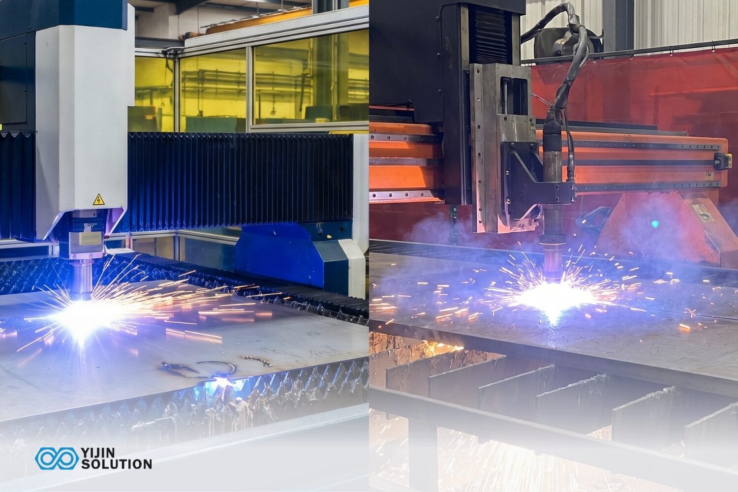
Laser cutting and plasma cutting are the two most common CNC processes for cutting sheet metal. They look similar on a capability sheet: both run on CNC, both cut steel, and both handle production batches. In practice however, they operate in different territory, with different tolerance bands, thickness limits, and cost profiles.
Choosing between them affects more than the cut itself. The process selection shapes edge quality, downstream bending and finishing work, scrap rates, and total cost per part. Getting it right at the sourcing stage is cheaper than correcting it later in the run.
This guide covers how each process works, where the differences matter, and how to choose between them for a sheet metal job.
Laser Cutting vs. Plasma Cutting: Quick Comparison
The full picture at a glance. Every row below is explained in the sections that follow.
| Attribute | Corte por láser | Corte por plasma |
|---|---|---|
| Process type | Focused beam melts and vaporizes material. Thermal, non-contact. | Ionized gas arcs melt conductive metal. Thermal & electrical. |
| Typical tolerance range* | ±0.05 to 0.2 mm, varies by material and thickness. | ±0.25 to 1.0 mm. HD plasma at the narrower end. |
| Max thickness, steel | ~25 mm fiber laser; ~20 mm CO2 | 50 to 150+ mm, depending on system amperage. |
| Cut edge quality | Clean, square, minimal dross. Often no secondary finishing. | 1 to 3° bevel, some dross. May need grinding or cleanup. |
| Speed on thin sheet, under 6 mm | 2 to 5× faster than plasma on thin gauge. | Slower than laser on thin sheet. |
| Speed on thick plate, over 20 mm | Slower; pierce time climbs above ~20 mm. | Faster; throughput advantage meaningful above 12 to 20 mm. |
| Equipment cost | High; fiber laser systems typically cost 2 to 5× more than plasma. | Lower; HD plasma is an accessible entry cost. |
| Operating cost | Higher per hour: gas, power, optics. | Lower per hour on thick plate. |
| Materiales | Metals and non-metals. Needs a clean, flat surface. | Conductive metals only. Tolerates rust, scale, and coatings. |
| Lo mejor para | Thin-to-medium precision sheet, complex profiles, tight-tolerance assemblies. | Thick structural plate, budget-sensitive cutting where tolerance allows. |
* Achievable tolerances depend on material, sheet thickness, machine setup, and part geometry. Figures shown are indicative ranges for commercial systems.
How does Laser Cutting Work?
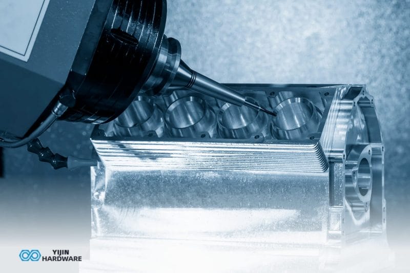
Laser cutting is a thermal process that uses a focused, high-energy beam to melt, burn, or vaporize material along a programmed path. The precision it achieves is a geometry consequence, not a machine setting you dial in.
A focused laser beam typically measures 0.1 to 0.3 mm in diameter at the focal point. That focus diameter directly determines the kerf width. A narrower kerf means the cut follows the programmed path more closely, with less room for material deviation along the edge. Laser holds tighter tolerances than plasma because the heat source is smaller, more geometrically stable, and more controllable.
Assist gas is where edge quality gets decided. Nitrogen produces clean, oxide-free edges on stainless steel. It’s the right choice for medical, cosmetic, and precision parts that skip secondary cleaning entirely. Oxygen accelerates cutting speed on mild steel but leaves a slightly oxidized edge. Compressed air works for cost-sensitive applications, though at the expense of edge quality. Wrong gas choice adds a finishing step that wouldn’t otherwise exist.
Three laser types matter in sheet metal production. Fiber lasers are the dominant platform, faster on thin metals, more reliable on reflective alloys like aluminum and copper, and lower running cost than CO2. CO2 lasers remain versatile across non-metals and metals; they are well-suited for 0.5 to 20 mm mild steel. Nd:YAG systems exist, but fiber has largely displaced them in commercial sheet cutting.
Fiber lasers cut mild steel up to approximately 25 mm in commercial settings, and the achievable tolerance tightens on thinner material because thermal input is easier to control. Batch repeatability across a production run depends on machine calibration, material consistency, and setup. The laser specification alone doesn’t guarantee it.
Laser’s narrow kerf, usually cited as a pure advantage, creates a production problem on thick plates. Above approximately 16 mm, parts bind in the sheet skeleton. The kerf is too narrow for them to drop cleanly, so they have to be knocked out manually, slowing throughput and requiring operator attention.
How does Plasma Cutting Work?
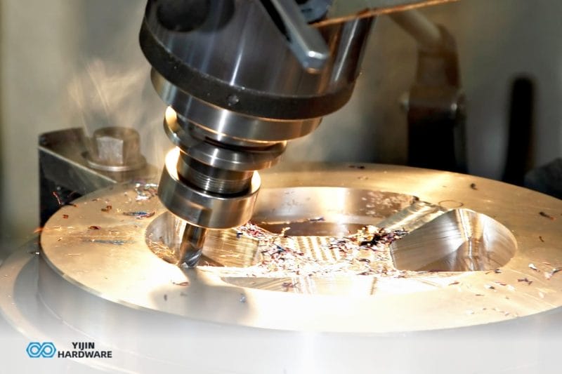
Corte por plasma forces pressurized gas through a constricted nozzle, creating an electrical arc that ionizes the gas into a plasma jet hot enough to melt through electrically conductive metals. That qualifier, electrically conductive, defines the entire process boundary. Plasma cannot cut non-conductive materials, and there’s no workaround for it.
The precision characteristics trace to the same physics. A plasma arc is wider and less geometrically controlled than a focused laser beam. Arc diameter and variability in the plasma jet’s edge behavior determine kerf width and edge straightness. The wider tolerance band is a physical consequence of not being able to focus an arc to the same geometric stability as a beam.
Two system types define the landscape. Conventional plasma uses lower-cost equipment and produces a wider kerf and rougher edge, suited for structural plates where tolerance requirements are loose. High-definition, or HD, plasma uses tighter nozzle geometry to produce a narrower kerf and better edge quality, closing the gap with laser on plate up to approximately 20 mm. HD plasma with True Hole technology can produce bolt-ready holes on mild steel, with a minimum hole diameter equal to the material thickness, at a 1:1 ratio minimum.
Conventional plasma handles material from 1 mm to 50+ mm. HD plasma is most effective between 6 to 38 mm on steel, and above 25 mm, plasma becomes the primary economical option for structural steel cutting. The heat-affected zone, or HAZ, runs wider than laser because more thermal energy deposits around the cut. On a thin sheet, that can mean minor distortion at the edge. On thick structural plates, it’s acceptable because tolerances are looser and secondary finishing is already planned.
Plasma also cuts through rust, mill scale, painted surfaces, and material stored outdoors. This is a daily operational advantage that the tolerance conversation tends to overshadow. Laser requires a clean, flat, properly stored sheet. Scale, coatings, and surface contamination can cause cutting failures or demand a pre-cut cleaning pass. Structural fabrication shops receiving material with mill scale or pulling stock from outdoor racks feel this difference every shift.
Laser Cutting vs. Plasma Cutting: Key Differences Explained
Each dimension below is a buyer decision, not just a technical observation.
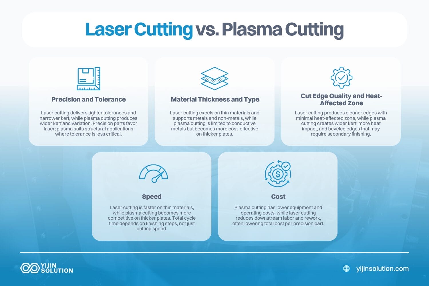
Precision and tolerance
The tolerance gap traces directly to process physics. A laser’s focused beam produces a kerf 0.1 to 0.3 mm wide. A plasma arc, even an HD one, produces a kerf that runs 1 to 3 mm wide on conventional systems, narrowing to approximately 0.5 to 1 mm with HD plasma. Wider kerf means more geometric variation along the cut path. It’s physics, not a quality judgment.
In practical numbers: laser cutting achieves tolerances in the ±0.05 to 0.2 mm range on sheet metal, depending on material and thickness. HD plasma narrows to ±0.25 to 0.5 mm on thicker plate, and conventional plasma runs wider at ±0.5 to 1.0 mm depending on the system and conditions. All ranges are approximate. Actual achievable tolerance depends on geometry, thickness, and machine setup.
Parts requiring tight-fitting assemblies, threaded inserts, or press-fit features get more consistent results from laser. Structural parts with looser dimensional tolerance and higher throughput demands are plasma territory.
Material thickness and type
Laser cutting is most cost-effective on steel sheets up to 25 mm, performing best under 12 mm. Above 12 to 20 mm, plasma becomes increasingly competitive on cost per cut.
Laser cuts metals and non-metals: acrylic, wood, rubber, ceramics. Plasma requires electrical conductivity and cannot process non-metallic materials. A plasma torch on an acrylic sheet produces nothing useful.
Plasma also has a minimum hole diameter constraint worth knowing about: it cannot accurately cut holes smaller than approximately 2× the material thickness without True Hole technology. Even with True Hole, the minimum is 1:1, meaning the hole diameter must equal the material thickness.
A 5 mm hole in a 10 mm plate isn’t accurately achievable with conventional plasma, which forces secondary drilling that adds cost and time. Laser can cut 2 mm holes in a 10 mm plate cleanly. For designs with dense hole patterns, small fastener holes, or precision slot features, this constraint may determine the process choice before tolerance or cost even enter the conversation.
Cut edge quality and the heat-affected zone
Laser produces a narrow kerf of roughly 0.1 to 0.3 mm on thin sheet, a minimal heat-affected zone, and edge quality that typically eliminates secondary deburring on clean cuts. Parts come off the table ready for the next operation.
Plasma produces a wider kerf of roughly 1 to 3 mm on conventional systems, narrower with HD plasma, and a broader HAZ. On a thin sheet, the wider HAZ can cause surface oxidation and minor distortion. Plasma cut edges carry a bevel angle of approximately 1 to 3 degrees, wider on thicker plate. Parts feeding directly into a weld fixture or bolt assembly may need that taper ground down or compensated in the design.
Cosmetic parts, plated surfaces, anything going straight to a press brake: laser reduces rework cost downstream. Structural parts without an edge finish specification absorb plasma’s characteristics without issue.
Velocidad
Modern fiber lasers cut 2 to 5× faster than plasma on sheets under 6 mm. Above 6 mm, plasma speed becomes competitive, and above 20 mm, plasma is typically faster at equivalent power levels.
However, cutting speed and cycle time are different things. Laser’s cleaner edge often removes a finishing step, changing the total time comparison significantly on precision parts that would otherwise need deburring after plasma.
Pierce time matters too on thick plates: above approximately 20 mm, plasma pierces faster, and on large nesting jobs the aggregate throughput advantage adds up quickly. It’s worth evaluating the full cycle, not just the minutes the machine is running.
Coste
Fiber laser systems are typically 2 to 5× more expensive than comparable HD plasma systems. A 6 kW fiber laser with a basic pallet changer runs in the $600,000 – $800,000 range. A high-definition plasma system lands around $250,000. Plasma consumables, like electrodes and nozzles, also cost less per hour than laser optics and gas.
Laser justifies its higher per-hour cost through tolerance, edge quality, and material versatility. On precision parts that accumulate rework and finishing after plasma cutting, laser’s total cost per conforming part is often lower.
Most comparisons skip the grinding labor. Plasma dross means someone is always grinding parts. A worker spending four hours a day on dross removal at $25/hour adds up to approximately $25,000 per year in labor cost. High-definition plasma systems like the Hypertherm XPR series can dramatically reduce that grinding time on appropriate materials, but the cost still shows up somewhere. Laser-cut parts on appropriate thicknesses go directly to the next operation.
The press brake workflow matters too. Laser-cut edges are press-brake-ready: straight to bending without edge preparation. Plasma-cut edges on thinner sheets often need grinding before bending to prevent cracking at the bend radius and ensure consistent bend development. Shops running both process types through the same press brake feel that upstream edge prep time accumulates across a shift. The cutting decision affects the full fabrication flow.
Material Compatibility: What Can Each Process Cut?
Material type often settles the process question before cost or tolerance even enter the picture. Plasma’s conductivity requirement is a hard limit, and better equipment doesn’t change it.
| Material | Corte por láser | Corte por plasma | Notas |
|---|---|---|---|
| Mild steel | Yes, CO2 and fiber | Yes, all system types | Oxygen assist gas for laser; plasma dominant on plate over 20 mm |
| Acero inoxidable | Yes, nitrogen assist is preferred | Yes. HD plasma for quality; conventional for structural. | Nitrogen-assist laser gives oxide-free edges; plasma leaves bevel and HAZ |
| Aluminio | Yes, fiber laser is preferred | Yes, with appropriate gas and parameters | Fiber laser handles reflectivity well; plasma tolerates mill scale |
| Copper and brass | Yes, fiber laser | Yes, conductive metal | Fiber laser handles reflective metals reliably; CO2 requires specialist setup |
| Titanio | Sí | Sí | Both work; laser preferred for precision aerospace applications |
| Acrylic and plastics | Yes, versatile | No. Non-conductive. | Process physics limit. Plasma cannot cut non-metals. |
| Wood and rubber | Yes, CO2 and fiber | No. Non-conductive. | Laser only. |
Modern fiber laser systems handle copper and brass reliably. This was a limitation of older CO2 systems that no longer constrains a well-equipped fiber laser shop. Plasma stays limited to conductive metals regardless of system upgrade. Material arriving rusted, scaled, or coated? Plasma handles it without pre-cleaning. Laser does not.
When to Choose Laser Cutting vs. Plasma Cutting
Process selection rests on three variables: material thickness, required tolerance, and project budget.
| Scenario | Recommended Process | Razón |
|---|---|---|
| Thin-gauge stainless steel or aluminum, 6 mm or under | Laser | Narrow kerf, clean edge, fast cycle time |
| Structural steel plate above 12 to 20 mm | Plasma | Cost per cut and throughput favor plasma; tolerance requirements typically allow it |
| Complex 2D geometry or intricate profiles | Laser | Fine detail, tight corner radii, and small hole accuracy require laser kerf width |
| Budget-sensitive, non-critical structural cuts | Plasma | Lower equipment and operating cost when tolerance is not the priority |
| Medical, aerospace, or tight-tolerance assemblies | Laser | Tolerance, edge quality, and traceability requirements favor laser |
| Non-metal sheet: acrylic, wood, composites | Laser | Plasma cannot process non-conductive materials |
| High-volume structural brackets and frames | Plasma for thick, Laser for thin | Choose by thickness: laser for thin gauge, plasma for structural plate |
| Designs with small holes, under 2× material thickness | Laser | Plasma minimum hole diameter constraint makes laser the only viable option |
Choose Laser Cutting When…
- Your material is thin to medium gauge, under 12 mm. Especially stainless steel, aluminum, or coated sheets.
- Tolerance requirements are tight. Assemblies requiring press fits, threaded inserts, or mating features under ±0.2 mm.
- Your part has small holes, intricate profiles, or detailed 2D geometry where plasma’s kerf width would cause dimensional error.
- Edge quality matters downstream. Cosmetic parts, plated surfaces, or parts going directly to a weld fixture without edge prep.
- Your material includes non-metals like acrylic, composites, rubber, or wood alongside metal components.
Choose Plasma Cutting When…
- Your material is a thick structural plate, above 12 to 20 mm on steel, where plasma throughput and cost advantage is real.
- Tolerance requirements allow it. Structural parts where ±0.5 mm or looser is acceptable.
- All your material is conductive metal and you have no need for non-metal cutting.
- Budget is constrained. Lower equipment and operating cost make plasma the more accessible option.
- Your material arrives imperfect. Rusted, scaled, or coated stock from outdoor storage is plasma-compatible without pre-cleaning.
When to Use Both: The Hybrid Workflow
Some projects use plasma and laser in sequence. Plasma rough-cuts large plate blanks quickly and economically. Laser then cuts precision features like bolt holes, intricate slots, and close-tolerance profiles into the pre-cut blanks as secondary operations. This workflow is common in agricultural equipment, structural steel, and heavy industrial fabrication, where most of the part is structural plate, but specific features need laser accuracy.
Combination cutting machines that integrate both processes on one table do exist. Dedicated machines that do one job well tend to outperform them in throughput. A fabrication partnership that handles both plasma and laser processes internally often finds it more cost-effective to run plasma first and then laser, rather than operating either process in isolation.
Industry Applications of Laser and Plasma Cutting in Sheet Metal Fabrication
What you’re making matters as much as how thick the material is.
Automotive production uses laser cutting for body panels, brackets, and EV battery enclosure components where tolerances are tight and cosmetic standards are high. Plasma handles structural subframes and chassis plates where speed matters more than edge finish.
Aerospace and defense rely on laser for precision brackets, housings, and structural skins in Aluminum 6061, Stainless Steel 316L, and Titanium Grade 5. Plasma is rarely specified for tight-tolerance aerospace sheet work.
Medical device manufacturing runs almost entirely on laser. Surgical instrument components, medical enclosures, and thin-gauge stainless parts need tight tolerances and burr-free edges.
Industrial equipment is the category that uses both processes side by side. Laser for precision control panels and mounting plates, and plasma for thick structural weldments, frames, and support structures.
Consumer electronics and robotics use laser cutting for aluminum chassis, heat spreaders, and precision sheet frames where cosmetic and dimensional standards are high.
Talk to Yijin About Your Sheet Metal Project
Choosing between laser and plasma is rarely obvious from a CAD file alone; it depends on tolerance, thickness, volume, and what happens downstream.
Solución Yijin runs both processes in-house and recommends the right one at the engineering review stage, before cutting begins. Our sheet metal team works across automotive, aerospace, medical, and industrial applications, backed by ISO 9001, IATF 16949, AS9100D, and ISO 13485 certifications covering each of those sectors.
Upload your CAD files for a free DFM review and quote within 24 hours.
FAQs on Laser Cutting vs. Plasma Cutting for Sheet Metal
Can I switch from plasma to laser mid-project if tolerances turn out tighter than expected?
It depends on how far along the project is. If cutting hasn’t started, switching is usually straightforward since the fabricator re-nests parts for the laser table and requotes.
Once plasma cutting is underway, parts already cut to plasma tolerances can’t be retroactively tightened. You’d need to recut those parts on laser, which means paying twice for that portion of the run.
How do I spec laser cutting vs plasma cutting on a drawing?
Most fabricators don’t expect a cutting process callout on the drawing itself. What they need are the tolerance values, edge finish requirements, and any notes about downstream operations like welding or bending. If a feature requires ±0.1 mm, the fabricator knows that’s laser territory. If a structural bracket calls for ±1.0 mm, plasma is on the table.
Does laser cutting work for one-off prototypes, or is it only cost-effective at volume?
Laser cutting is one of the more prototype-friendly processes in sheet metal fabrication. There’s no tooling cost, minimal setup time, and parts cut directly from a CAD file. A single prototype costs more per part than a production run because setup and programming time get absorbed by one unit instead of hundreds, but that applies equally to plasma.
What file formats and design practices make quoting faster?
STEP files are the standard for quoting sheet metal parts. They preserve 3D geometry, bend information, and feature detail that a fabricator’s nesting software can read directly.
DXF and DWG files work for flat-pattern parts but lose thickness and bend data, which means the fabricator has to ask follow-up questions or make assumptions. PDFs of drawings are useful as a reference alongside the 3D file, not as a replacement for it.
Volver arriba: Laser Cutting vs. Plasma Cutting for Sheet Metal: Which One does Your Project Need?