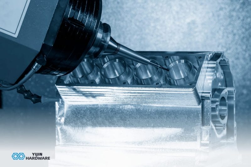

The sheet metal manufacturing process converts flat metal stock into precision parts through a controlled sequence of cutting, forming, joining, and finishing operations. Engineers across the automotive, aerospace, medical, and industrial sectors rely on it for enclosures, brackets, panels, and structural components.
Sheet metal has been shaped by hand for centuries, but modern fabrication bears little resemblance to that. CNC laser cutting holds tolerances to ±0.10 mm. Press brakes bend angles to within ±0.5°. A single fiber laser can cut profiles in seconds that would have taken hours with manual tools.
Sheet metal is highly cost-effective for flat and formed geometry, but it struggles with complex 3D contours, internal features, and tolerances tighter than ±0.10 mm. This guide walks through every stage of the process, the materials involved, what tolerances to expect, and how to choose between sheet metal and alternative processes.
What is Sheet Metal Manufacturing?
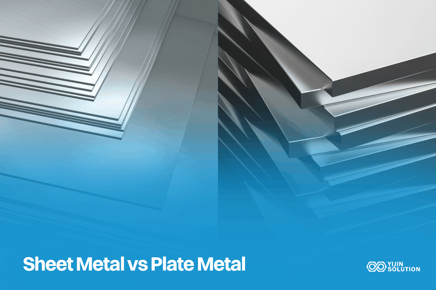
Sheet metal manufacturing is the fabrication of metal parts from flat, thin stock through processes that cut, form, join, and finish the material into functional components. The stock itself is between 0.5–6 mm thick for most industrial applications, though structural plate work can run thicker.
En sheet metal manufacturing market favors two broad categories. Forming operations shape the flat blank into its final geometry, and joining and finishing operations assemble multiple formed parts and protect the surface. The output is structural and enclosure components with consistent wall thickness, repeatable dimensions, and good surface finish – all achieved without the high tooling cost of die casting.
How is sheet metal made?
Sheet metal starts as raw metal billets or slabs. These are hot-rolled at a high temperature to reduce thickness and increase length. For tighter dimensional control and a cleaner surface, the hot-rolled coils go through cold-rolling at room temperature. Cold-rolling hardens the metal, improving its strength and surface quality.
Material grade matters from this point forward. Mild steel sheet offers the best cost-to-formability ratio. Stainless Steel 304 and 316L provide corrosion resistance. Aluminum 5052 and 6061 give you lightweight formability and anodizing compatibility. If electrical conductivity is the primary requirement, copper sheet is mainly used. The material grade selected here directly affects downstream bend radii, cutting behavior, and surface finishing options.
The Sheet Metal Manufacturing Process: Step by Step
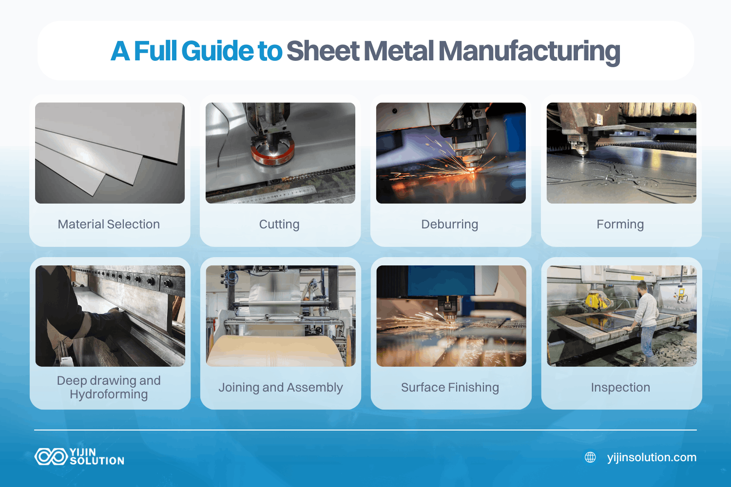
While specific operations vary by part geometry and material, every sheet metal fabrication job follows this core sequence. The table below summarizes the steps.
| Paso | Stage Name | What Happens | Key Quality / Cost Lever |
|---|---|---|---|
| 1 | Selección de materiales | Choose the alloy, material grade, and sheet thickness based on strength, corrosion, and weight requirements. | Wrong grade = rework; confirm with DFM review first. |
| 2 | Corte | The sheet is cut to blank size using laser, plasma, waterjet, or punching. | The method affects edge quality, the heat-affected zone, and the cost. |
| 3 | Desbarbado | Removes sharp edges and burrs from cut profiles before forming. | Skipping deburring causes forming defects and handling injuries. |
| 4 | Forming / Bending | Blank is formed to shape using press brakes, roll forming, or stamping dies. | Bend radius and springback determine dimensional accuracy. |
| 5 | Deep Drawing / Hydroforming | For enclosed shapes, the metal is drawn over a punch under hydraulic force. | Wall thinning and tearing risk – requires DFM review. |
| 6 | Joining / Assembly | Formed parts are joined via welding, riveting, clinching, or adhesive bonding. | Joint strength and distortion control are critical for fit-up. |
| 7 | Acabado de superficies | Parts are cleaned, coated, or treated with powder coating, anodizing, plating, or passivation. | Finish affects corrosion life and aesthetic acceptance. |
| 8 | Inspección | Dimensional and visual checks; CMM or optical measurement for critical features. | First Article Inspection confirms drawing compliance. |
Paso 1: Selección de materiales
The most common sheet metal materials are mild steel, stainless steel 304 and 316L, aluminum 5052-H32 and 6061-T6, and copper.
- Mild steel offers the best combination of machinability, weldability, and cost. It’s the default for structural brackets and enclosures in non-corrosive environments.
- Stainless Steel 316L is the right call for marine, medical, and chemical applications where chloride resistance matters.
- Aluminum 5052 bends cleanly without cracking, making it ideal for formed enclosures.
Sheet thickness directly affects what’s possible downstream. For most structural brackets and enclosures, 1.0–3.0 mm is the practical working range. Go thinner and you get lighter parts but a narrower process window for bending. Go thicker and cutting speed drops, bend forces increase, and minimum bend radii grow.
Step 2: Cutting
Cutting is where flat stock becomes a shaped blank. There are four main methods, each with different speed, edge quality, and cost profiles.
- Laser cutting delivers the best edge quality and detail, holding tolerances to ±0.10 mm across 0.5–20 mm steel. Fiber laser systems minimize the heat-affected zone, which is why thin-gauge stainless and aluminum cut cleanly without discoloration or hardening at the edge.
- Plasma cutting is faster and cheaper for thick plates above 8 mm, but the kerf is wider and edge accuracy is lower.
- Waterjet introduces no heat at all, which is useful for heat-sensitive alloys and composites. However, cycle times are slower.
- Punching and blanking are the right call for high-volume flat parts with standard hole patterns; tooling cost applies upfront but per-part cost drops quickly at volume.
| Método | Gama de espesores | Tolerancia | Calidad de los bordes | Lo mejor para |
|---|---|---|---|---|
| Corte por láser | 0.5–20 mm | ±0,10 mm | Excelente | Precision parts, thin to medium sheet |
| Corte por plasma | 3–80 mm | ±0.5–1.0 mm | Moderado | Thick plate, structural work |
| Corte por chorro de agua | 0.5–150 mm | ±0.10–0.25 mm | Muy buena | Heat-sensitive or thick materials |
| Punching / Blanking | 0.5–6 mm | ±0.10–0.20 mm | Bien | High-volume flat parts with repeated features |
Step 3: Deburring
Cut edges carry burrs and micro-sharp profiles that must be removed before forming. If you skip this step, burrs can crack the material at bend lines and create handling injuries downstream.
Belt grinding removes the oxide layer on stainless steel and leaves a clean, consistent edge. Tumbling works well for batches of small parts. Manual deburring is used where geometry prevents mechanical access.
Step 4: Forming and Bending
Press braking is the dominant bending method in sheet metal fabrication. A CNC press brake forces the blank against a die profile to form an angle. The key design rule: minimum inside bend radius must be at least 1× material thickness for mild steel, 1.5× for stainless steel, and 2× for Aluminum 6061-T6. Go tighter and the outer surface cracks.
Springback is the other variable to control. Formed metal tries to return toward its flat state after the press brake releases. The operator compensates this by overbending. How much bending is necessary depends on the material’s yield strength and temper; cold-rolled steel and hard-temper aluminum exhibit more springback than annealed material. Roll forming is a separate option for long, constant-profile parts like channels and structural frames. It’s more economical than press braking at high volumes for specific cross-sections.
Step 5: Deep drawing and Hydroforming
Deep drawing applies to enclosed geometry where bending alone can’t form the shape. A blankholder clamps the flat sheet while a punch draws the material into a die cavity. Wall thinning is the primary risk; maximum draw depth is typically limited to around 40–50% of the blank diameter before the part needs re-drawing. Exceed that ratio and the wall tears.
Hydroforming replaces the rigid punch with pressurized fluid. This approach conforms the metal to complex die surfaces more evenly, reducing wall thinning and enabling shapes that would tear in conventional drawing.
Both processes require upfront tooling and only become economical above a certain volume. A DFM review at the design stage often identifies whether a simpler bent form can achieve the same geometry and save tooling costs.
Step 6: Joining and Assembly
Sheet metal assembly uses four main joining methods.
- TIG welding produces the highest weld quality and is required for stainless steel and aluminum in structural or cosmetic applications. It’s slower and costlier than MIG but leaves a cleaner, lower-distortion joint.
- MIG welding is faster for mild steel.
- Spot welding suits thin steel sheet assemblies well; it’s the standard for automotive body panels where speed and repeatable nugget strength matter.
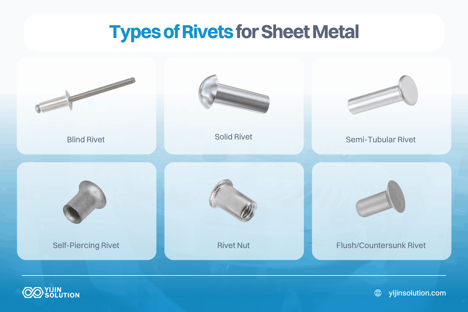
- Riveting and mechanical clinching introduce no heat, making them suitable for mixed-material assemblies and any part where weld distortion would throw tolerances out.
Weld distortion is one of the most common causes of out-of-tolerance sheet metal assemblies. Joint design, fixturing, and weld sequence all affect how much the part moves during welding.
Step 7: Surface finishing
Surface finishing protects the metal and, in many applications, meets aesthetic or regulatory requirements. Powder coating applies a thermoset polymer electrostatically and cures it at 356–392°F, producing a durable color finish at a typical thickness of 60–120 µm. It works on steel and aluminum.
Anodizing creates an electrochemical oxide layer on aluminum, improving corrosion resistance and surface hardness. Type II anodizing builds 5–25 µm; Type III hard anodize builds 25–75 µm.
Passivation is the correct finishing process for stainless steel, not powder coating. The ASTM A967 process removes free iron from the surface with a citric or nitric acid bath, restoring the chromium oxide passive layer that gives stainless steel its corrosion resistance.
Electroplating adds corrosion protection and wear resistance to steel parts. Bead blasting provides a uniform matte surface texture before plating or anodizing. Specify only the finish the application actually requires; over-specifying adds lead time and cost without adding function.
Step 8: Inspection
Final inspection confirms that the fabricated parts match the engineering drawing. Calipers and gauges handle most dimensional checks. Coordinate Measuring Machine inspection handles complex features and tight callouts. Optical measurement systems work well for 2D profile verification on laser-cut parts.
The First Article Inspection is the standard for new part numbers. The team fully measures the first production piece against every drawing callout before batch production continues. This catches setup errors before they propagate to a full production run.
What Tolerances Can Sheet Metal Fabrication Hold?
Tolerance capability depends on three factors: the process used, the material, and the part geometry.
| Proceso | Tolerancia de precisión | Tolerancia estándar | Typical Lead Time |
|---|---|---|---|
| Corte por láser | ±0,10 mm | ±0.20 mm | Prototyping: 3–7 days |
| Bending / Forming | ±0.20 mm | ±0.30 mm | Prototyping: 3–7 days |
| Sheet Metal Assembly | ±0.30 mm | ±0.50 mm | Production: 7–15 days |
| Maximum Part Size | 2,440 × 1,220 mm | — | — |
Material and part geometry shift these numbers in practice:
- Material: Stainless steel hardens during forming, which widens the practical tolerance band for bent features compared to mild steel. Aluminum alloys vary too. 5052-H32 bends more predictably than 6061-T6, which has a higher springback coefficient.
- Geometría parcial: Complex geometry accumulates tolerance stack-up across multiple bends, flanges, and weld joints. A single laser-cut profile holds ±0.10 mm easily. A multi-bend assembly with welded sub-components may realistically land at ±0.50 mm or wider at the final assembly level, even with good fixturing.
Which Materials are Used in Sheet Metal Fabrication?
Material choice affects every downstream step, including bend radii, cut speed, weld procedure, and finishing compatibility. Here’s how the common options compare.
- Mild steel is the most cost-effective sheet metal material and the default for structural brackets, enclosures, and machine guards in non-corrosive environments. It welds easily, bends cleanly, and accepts powder coating and electroplating well. It needs surface finishing for corrosion protection, as bare mild steel rusts in humidity.
- Stainless Steel 304 and 316L is preferred for medical, food processing, and marine applications. Both grades are harder to form than mild steel. Also, springback is higher and minimum bend radii are wider. 316L adds molybdenum, which significantly improves chloride resistance over 304. For parts that will see saltwater or aggressive cleaning chemicals, 316L is worth the cost premium.
- Aluminum 5052-H32 and 6061-T6 offer a lightweight, naturally corrosion-resistant alternative. 5052 has better ductility for deep drawing and formed enclosures. 6061-T6 is stiffer and machines well, making it the right choice for hybrid sheet metal and CNC assemblies. Both grades anodize cleanly.
- Copper and brass are used where electrical conductivity or a combination of corrosion resistance and a decorative finish is required. Common in EMI shielding, heat exchangers, and precision hardware. Both are costlier per kilogram than steel or aluminum, so they’re specified only when the application justifies it.
| Material | Propiedades clave | Grados comunes | Aplicaciones típicas |
|---|---|---|---|
| Acero dulce | High strength, low cost, easy to weld | ASTM A1008, A1011 | Enclosures, brackets, structural frames |
| Acero inoxidable | Corrosion-resistant, hygienic | 304, 316L | Medical, food, marine, chemical |
| Aluminio | Lightweight, anodizable | 5052-H32, 6061-T6 | Aerospace panels, EV battery trays, electronics |
| Copper / Brass | High conductivity, decorative | C110, C260 | EMI shielding, heat exchangers, hardware |
Common Applications of Sheet Metal Fabrication
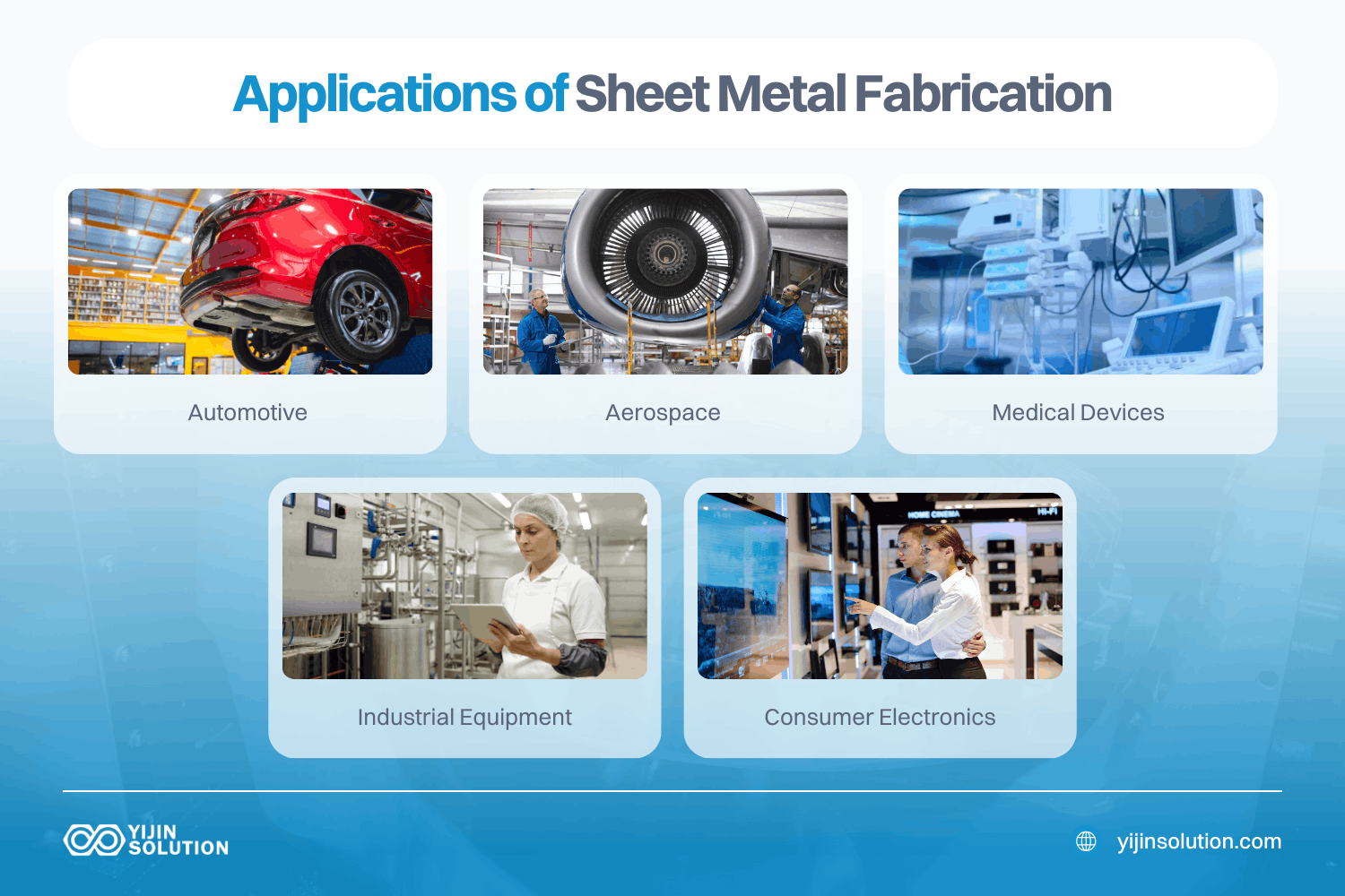
Sheet metal fabrication appears in almost every industry that needs formed metal parts. Here’s where it does the most work.
- Automóvil: Door skins, firewall panels, EV battery enclosures, and chassis brackets. Body panels use high-volume stamping; structural sub-assemblies use laser cutting and press braking for lower-volume, high-complexity work.
- Aeroespacial: Fuselage panels, avionics enclosures, brackets, and ducting. Full dimensional traceability is required at every step. Suppliers must carry AS9100D certification.
- Medical devices: Instrument housings, surgical cart frames, and diagnostic equipment enclosures. Stainless steel and anodized aluminum dominate. ISO 13485 quality system certification is expected from suppliers.
- Industrial equipment: Control cabinets, machine guards, HVAC ducting, and pump housings. Mild steel with powder coating is the standard combination for most industrial enclosure work.
- Consumer electronics: Laptop chassis, server rack panels, and LED light housings. Aluminum 5052 and 6061 are the materials of choice for heat dissipation and weight reduction.
Sheet Metal Fabrication vs. Other Manufacturing Processes
Choosing between sheet metal fabrication, Mecanizado CNC, and die casting comes down to part geometry, production volume, tolerance requirements, and upfront budget. The table below gives you a direct comparison of these factors.
| Attribute | Fabricación de chapas metálicas | Mecanizado CNC | Fundición a presión |
|---|---|---|---|
| Coste de utillaje | Low, with no hard tooling for laser/brake work | None for 3-axis; moderate for fixtures | Alta |
| Per-Part Cost | Bajo | Moderate to High | Alta |
| Per-Part Cost | Moderado | Alta | Bajo |
| Geometry | Flat / formed shapes, enclosures | Complex 3D, undercuts, internal features | Complex 3D, thin walls |
| Tolerancia | ±0.30 mm | ±0,05 mm | ±0.30 mm |
| Typical Lead Time | 3–15 days | 7–15 days | 25–35 days including tooling |
| Best Volume Range | 1–50,000+ parts | 1–10,000 parts | 5,000+ parts/year |
| Lo mejor para | Enclosures, brackets, panels | Precision machined components | High-volume non-ferrous parts |
Sheet metal is the right process for thin-walled parts, enclosures, brackets, and panels where the geometry can be achieved from flat stock at low-to-medium volumes.
CNC machining takes over when the part has complex 3D geometry, internal features, or tolerances tighter than ±0.10 mm.
Die casting becomes cost-competitive only when volume justifies the tooling investment and the geometry is too complex for sheet metal.
Key Design Rules for Sheet Metal Fabrication
Getting these rules right at the design stage eliminates the most common causes of rework, scrap, and cost overruns.
- Minimum inside bend radius: mild steel = 1× material thickness; stainless steel = 1.5×; Aluminum 6061-T6 = 2×. Go tighter and the outer surface cracks during forming.
- Minimum flange length: typically 4× material thickness. Shorter flanges can’t be clamped accurately in a press brake because the blank slips and the angle is wrong.
- Hole-to-edge distance: keep holes at least 1.5× material thickness from any edge. Closer than that, and the metal tears out around the hole during punching.
- Bend relief cuts: required wherever a bend runs close to a notch or edge. Without relief cuts, the transition tears during forming.
- Consistent material thickness: avoid mixing different sheet thicknesses in a single formed part. Each thickness requires a new setup and separate tooling verification.
- Standard tooling angles: use 90° and 45° bends wherever possible. Non-standard profiles require custom die inserts and drive up tooling costs.
- Leave stock for CNC: if a feature needs to hold tighter than ±0.10 mm, add machining stock to the design and machine it after forming. Trying to form sub-0.10 mm directly produces scrap, not precision.
Advantages of Sheet Metal Fabrication
- Low tooling cost compared to die casting and injection molding. It’s suitable for prototypes, engineering samples, and small production batches without upfront die investment.
- Fast lead times. At Yijin Solution, our sheet metal prototyping runs 3–7 days; production batches ships in 7–15 days.
- Wide material and thickness range, from 0.5 mm aluminum sheet to 6 mm structural steel plate.
- Scalable from prototype to production. Laser cutting and press brake work require no re-tooling as volume production grows.
- Good strength-to-weight ratio, particularly in aluminum. Sheet metal structures are lighter than equivalent solid machined components.
Disadvantages of Sheet Metal Fabrication
- Geometry is limited to what can be cut and formed from flat stock. Highly complex 3D shapes, internal features, and undercuts require CNC machining or casting.
- Tolerances are wider than CNC machining. Features tighter than ±0.10 mm need secondary CNC operations after forming.
- Springback and weld distortion require careful process control and fixturing. Parts that aren’t properly fixtured during welding can drift out of tolerance.
- Per-part cost at very high volumes may be higher than die casting once tooling is amortized.
Choosing the Right Sheet Metal Fabrication Partner
Sheet metal fabrication is only as reliable as the supplier executing it. The process involves too many interdependencies – material behavior, bend sequences, weld distortion, surface finish compatibility – for a fragmented supply chain to manage consistently. Once you’ve worked through the design rules, material selection, and tolerance requirements covered in this guide, the next decision is finding a partner with the process capability to execute them.
For teams that need sheet metal, our team at Solución Yijin is here to help you. Our engineering team runs a free DFM review on every new part before quoting — evaluating bend radii, hole placements, flange lengths, and material selection before anything is cut.
All fabrication happens in-house: fiber laser cutting, CNC press brake forming, TIG and MIG welding, surface finishing, and CMM inspection. Our facility holds AS9100D, IATF 16949, and ISO 13485 certifications, with full documentation packages and First Article Inspection reports available on request. Prototype lead times run 3–7 days; production batches ship in 7–15 days. Upload your CAD files for a free DFM review and quote within 24 hours.
Sheet Metal Manufacturing Process FAQs
What is the difference between sheet metal fabrication and stamping?
Sheet metal fabrication covers all processes used to cut, form, join, and finish flat metal stock. Laser cutting, press braking, welding, and surface treatment are all part of the process. Stamping is a specific subprocess where metal is pressed into a shape using a die and punch in a single high-speed stroke.
Stamping becomes cost-effective at high volumes, typically 10,000 parts or more, because the tooling cost spreads across the batch. Fabrication using laser cutting and press braking has lower setup costs and adapts easily to design changes. This means it’s the more economical choice for lower volumes and evolving designs.
What materials can be used in sheet metal fabrication?
The most common materials are mild steel, stainless steel 304 and 316L, aluminum 5052-H32 and 6061-T6, and copper alloys. Material selection depends on your mechanical requirements, environmental exposure, and surface finish compatibility. Confirm your material and finish combination with a DFM review before finalizing your design.
What tolerances does sheet metal fabrication hold?
Standard sheet metal tolerances run ±0.30 mm for most formed features. Precision laser-cut profiles reach ±0.10 mm. For tolerances tighter than ±0.10 mm, secondary CNC machining on the formed part is typically the right approach. Attempting to achieve sub-0.10 mm directly in sheet metal produces inconsistent results across a production run.
When should I use sheet metal fabrication instead of CNC machining?
Sheet metal works best for thin-walled parts, enclosures, brackets, and panels where the geometry is achievable from flat stock. The setup cost is low and the lead time is fast for parts in this category. CNC machining is the better fit for complex 3D geometry, internal features, or tolerances below ±0.10 mm. For hybrid designs, sheet metal forming and CNC machining can be combined: form the basic shape in sheet metal, then machine the tight-tolerance features.
Volver arriba: Sheet Metal Manufacturing Process: The Full Guide to Fabrication