
When a design is finalized and the team needs a functional part to test, the gap between a finished CAD file and a physical prototype is where timelines often stall. CNC rapid prototyping closes that gap. It turns a 3D model into a production-grade prototype, machined from the same metal or engineering plastic the final part will use, in days rather than weeks.
What follows is a practical look at how CNC prototyping actually runs on the shop floor: the step-by-step process, the materials and tolerances to expect, where it beats (and loses to) 3D printing and soft tooling, and how supplier choice moves the needle on cost and lead time.
What is CNC Rapid Prototyping?
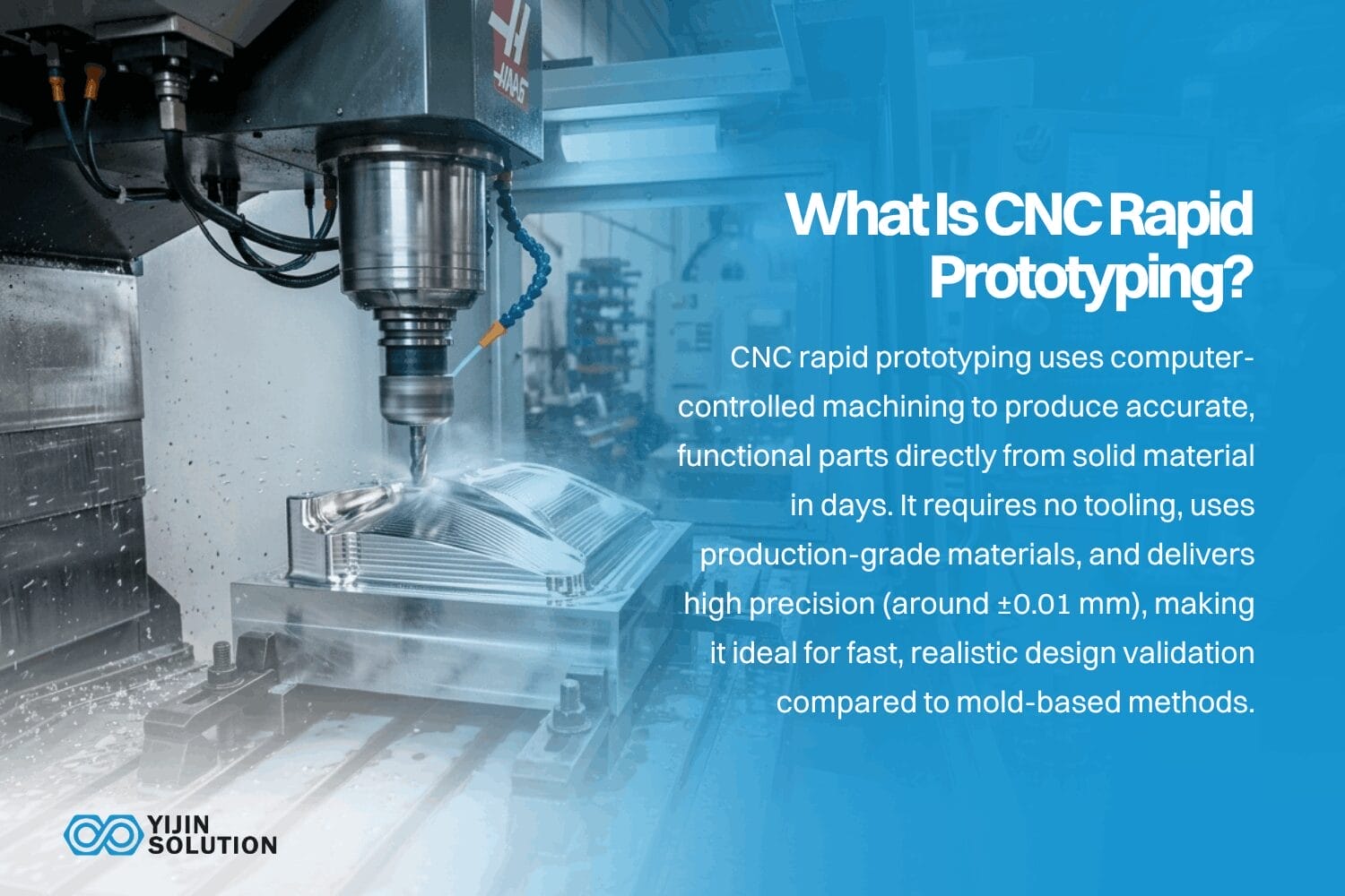
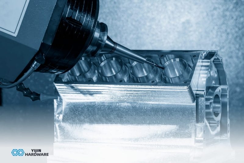
CNC rapid prototyping is a subtractive manufacturing process that uses computer-controlled machines to cut functional parts directly from solid material, delivering precision prototypes in days rather than weeks.
The output is not a concept model. It is a dimensionally accurate, structurally representative part made from the same or equivalent material as the intended production component. An Aluminum 6061 prototype behaves mechanically, thermally, and chemically like the production part because it is the same alloy, machined on the same class of equipment.
“Rapid” refers to the absence of dedicated tooling, molds, or dies. The machine works directly from the CAD file. This eliminates the tooling lead time that makes traditional prototyping impractical for early design iterations. Compared with the 8 to 20 weeks required for injection mold tooling, a CNC prototype machined in 3 to 7 days qualifies as fast. Compared with an FDM 3D print that finishes overnight, it is slower, but the CNC part arrives in production material at production tolerances.
The speed and accuracy of CNC prototyping depend on machine setup, fixturing, toolpath strategy, material behavior, and measurement, not just the equipment specification. On well-set-up CNC equipment, rapid prototypes commonly ship in seven days or fewer for standard parts, with achievable precision tolerances around 0.01 mm where the part geometry, material, and feature size support it.
How does CNC Rapid Prototyping Work?
The process moves through five stages, each with a direct effect on the quality and timeline of the finished prototype.
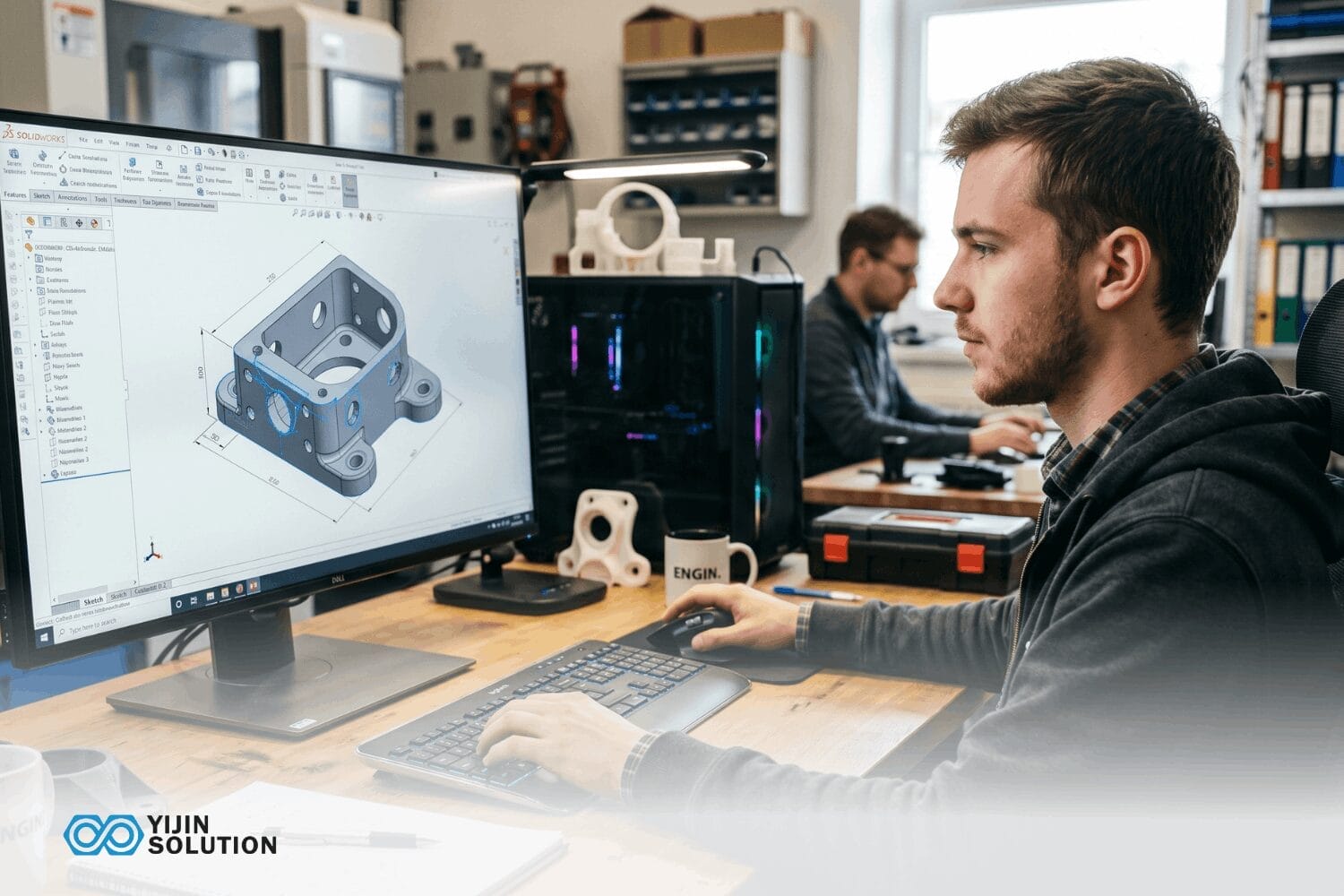
Step 1: CAD file and DFM review
The process begins when an engineer submits a 3D CAD file, typically in STEP or IGES format. The model defines every dimension, feature, and tolerance that the machinist will work to. Incomplete models or missing dimensions create delays because the shop has to stop and ask questions before programming can begin.
Before machining, the file should be reviewed for manufacturability. A DFM review checks for features that are difficult or expensive to machine: sharp internal corners, wall sections below minimum thickness, undercuts that require repositioning, and tolerances tighter than the part geometry can reliably hold. Catching these issues before machining is where most of the schedule and cost savings come from. A design that passes DFM can proceed directly to toolpath generation.
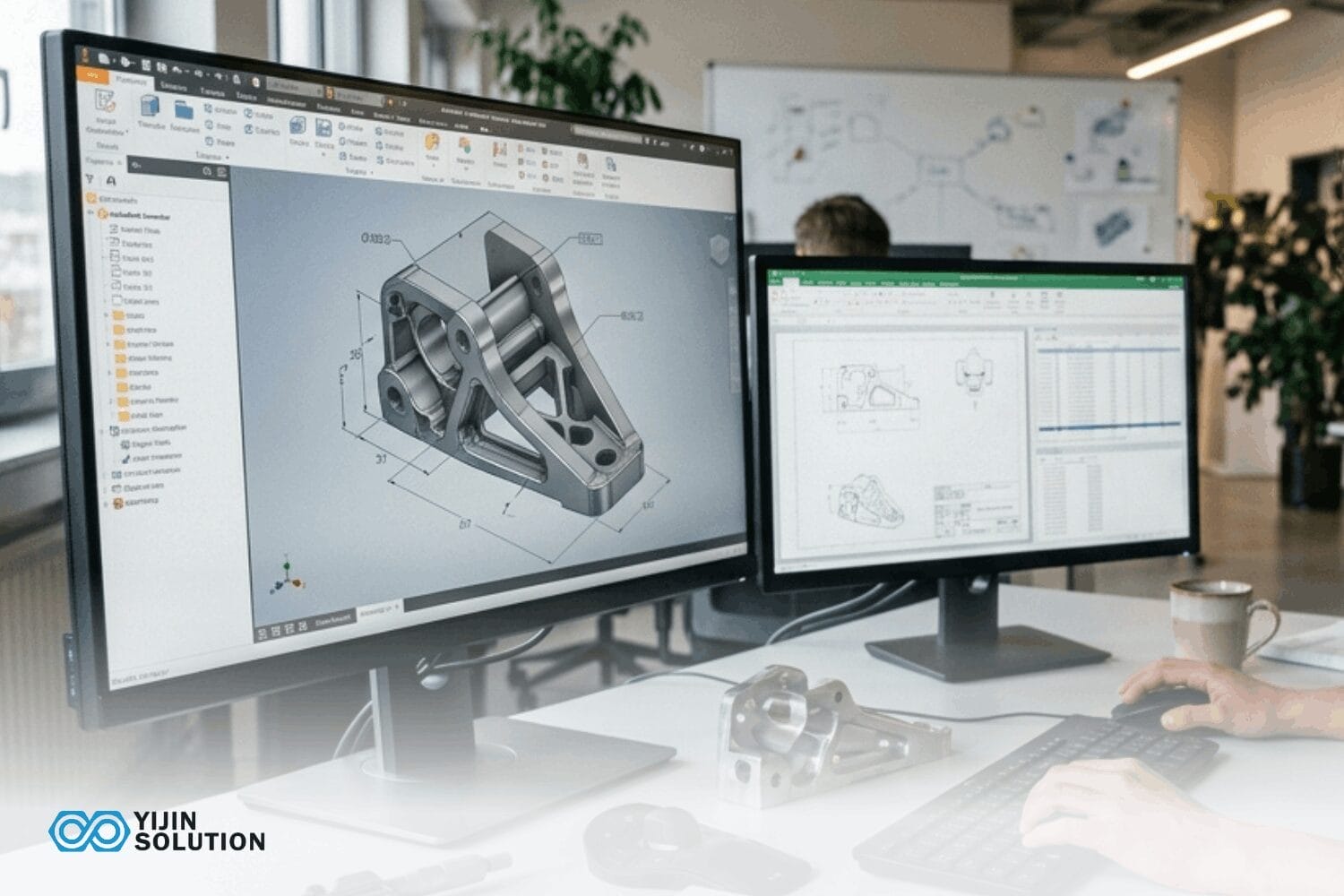
Step 2: CAM programming and toolpath generation
Once the design is approved, the CAD file is imported into Computer-Aided Manufacturing (CAM) software. The software generates the toolpaths: the precise cutting sequences, tool selections, and feed rates the CNC machine will follow.
For multi-axis machining, the CAM programmer determines how many setups are required. A 3-axis part may need only one fixture position, while a part with features on multiple faces may require a 4-axis or 5-axis approach to avoid multiple repositioning steps.
Toolpath quality directly affects surface finish, dimensional accuracy, and cycle time. Well-optimized toolpaths reduce vibration, extend tool life, and produce cleaner surfaces without secondary finishing. Programming time varies with complexity. A simple bracket might take 30 minutes. A multi-feature aerospace housing could take several hours. This step is a fixed cost that hits hard on single-part orders but drops to a fraction of the per-unit cost on small batches.
Step 3: Machine setup and fixturing
The material stock is secured on the CNC machine’s worktable or in a chuck for turning operations. Proper fixturing is one of the most underappreciated factors in prototype accuracy: a poorly fixtured workpiece introduces vibration and positional error regardless of how good the toolpath is.
For prototypes with tight tolerances or complex geometry, the setup engineer may need to design a custom fixture or soft jaw. This adds time but is often necessary to hold the part stable during cuts in difficult orientations. Machine calibration and tool offset verification are completed before cutting begins. For a 3-axis mill running Aluminum 6061, setup might take 30 to 60 minutes. A 5-axis job with multiple operations can take two hours or more.
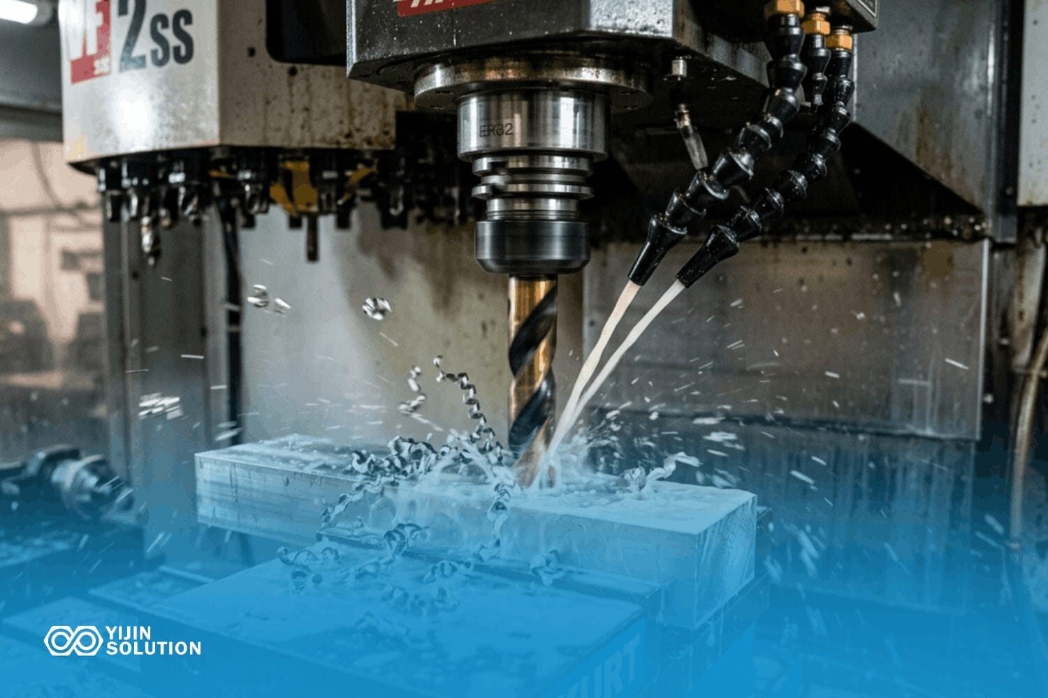
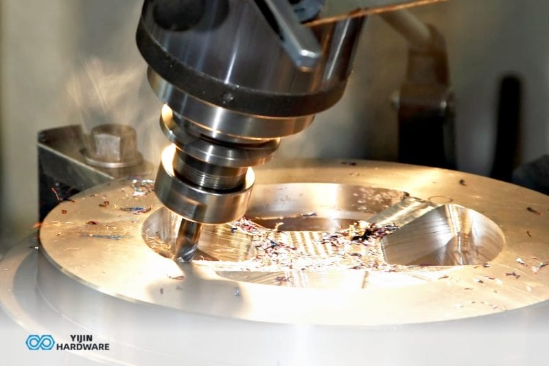
Step 4: Machining and in-process inspection
The CNC machine follows the programmed toolpaths, removing material systematically. For most prototype geometries, machining is completed in one or two setups, often within the same shift.
In-process measurement, using probing systems or manual gauging at key stages, catches dimensional drift before it propagates through the full part. This is especially important for tight-tolerance features such as bores, mating faces, and thread engagements. 5-axis machining centers can access complex geometry in a single setup, reducing repositioning errors and shortening cycle time for difficult parts.
Cycle time depends on material removal volume, surface finish requirements, and the number of features. Aluminum cuts fast, often at 15,000 RPM or more with aggressive feed rates. Stainless steel and titanium demand slower speeds, lighter cuts, and more frequent tool changes, all of which extend cycle time and cost.
Step 5: Post-processing and inspection
Machined prototypes typically require deburring, edge-breaking, and cleaning before measurement. Some applications require surface finishing such as anodizing, bead blasting, or electroless nickel plating. Secondary operations add lead time and cost, so it is worth specifying only what the prototype actually needs for testing.
Final inspection is performed against the CAD drawing tolerances using coordinate measuring machines (CMMs), image measuring systems, or manual gauging, depending on the feature type and tolerance class. Tolerance grades follow ISO 2768 for general machined part tolerances. Every prototype should ship with dimensional verification against the customer’s drawing tolerances.
Which CNC Processes are Used in Rapid Prototyping?
Rapid prototyping spans the same core CNC processes used in production: milling, turning, and combinations of both with secondary operations. The choice depends on part geometry and the tolerances the prototype needs to hit.
Fraisage CNC
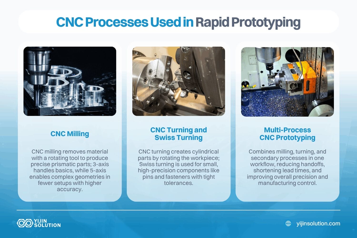
Fraisage CNC removes material from a fixed workpiece using a rotating cutting tool. It is the most common CNC prototyping method for prismatic parts, enclosures, plates, brackets, and components with complex pocket geometry.
3-axis milling is sufficient for most flat-faced, stepped, and pocket-featuring parts. 4-axis and 5-axis milling add rotational capability, allowing the tool to access angled faces, compound curves, and features that would otherwise require multiple setups. 5-axis prototyping is particularly suited to aerospace components, medical implant profiles, and automotive parts where compound geometry needs to be held in a single fixturing, reducing setup time and positional error across features.
CNC turning and Swiss turning
CNC turning produces cylindrical and rotationally symmetric parts: shafts, bushings, threaded inserts, and round housings. The workpiece rotates against a stationary cutting tool. Turning is faster than milling for round geometries and produces an excellent surface finish on outer diameters.
Swiss-type CNC lathes are particularly suited to small-diameter, high-precision cylindrical parts with tight length-to-diameter ratios. They are standard for prototyping custom fasteners, precision pins, and miniature medical components.
Multi-process CNC prototyping
Complex prototypes often require both milling and turning operations, plus secondary processes such as thread milling, gun drilling, or EDM for features that standard cutting tools cannot reach. Working with a supplier that runs all processes in-house eliminates the coordination overhead of managing multiple subcontractors and the lead time gaps between handoffs.
What Materials Can Be Used in CNC Rapid Prototyping?
CNC machining works from standard stock material. No specialized feedstock is required, unlike selective laser sintering or direct metal laser sintering. This means the prototype can be machined from the exact alloy or polymer grade specified for production, ensuring test results transfer directly. The table below covers the most common prototyping materials and their key considerations.
| Matériau | Grade Examples | Propriétés principales | Common Prototype Applications | CNC Machinability Note |
|---|---|---|---|---|
| Aluminium | 6061-T6, 7075-T6 | Lightweight, strong, corrosion-resistant, excellent thermal conductivity | Enclosures, brackets, heat sinks, structural frames, aerospace fittings | Excellent. Machines fast at high RPM. Most shops stock 6061 in standard sizes. |
| Acier inoxydable | 304, 316L | High corrosion resistance, good strength, biocompatible in 316L | Food processing parts, marine hardware, medical housings, chemical equipment | Moderate. Machines at roughly half the speed of aluminum. Higher tool wear increases the per-part cost. |
| Titane | Grade 5, Ti-6Al-4V | High strength-to-weight ratio, biocompatible, heat-resistant | Aerospace structural parts, medical implants, high-performance fasteners | Difficult. Slow speeds, high tool wear, requires careful thermal management. The cost runs 3 to 5 times that of aluminum. |
| Laiton | C360, C260 | Excellent electrical conductivity, corrosion-resistant, decorative finish | Electrical connectors, valve components, decorative hardware | Excellent. Free-machining grades produce clean chips and a fine surface finish. |
| Cuivre | C110, C101 | Superior thermal and electrical conductivity | Heat exchangers, busbars, thermal management components | Good. Softer than brass; requires sharp tooling to avoid burring. |
| ABS | Objectif général | Good impact resistance, dimensional stability, easy to machine | Consumer electronics housings, fit-check models, functional prototypes | Excellent. Machines cleanly and holds tolerances well. |
| Polycarbonate | Objectif général | Transparent, high-impact resistance | Optical housings, protective covers, light guides | Good. Sensitive to heat buildup; requires controlled feed rates. |
| PEEK | PEEK 450G, PEEK GF30 | High-temperature resistance, chemical inertness, excellent mechanical properties | Aerospace bushings, medical device components, chemical seals | Moderate. Expensive stock, around $200 to $500 per kg. Demands slower feeds. |
| Delrin / POM | Delrin 150, Delrin AF | Low friction, high stiffness, excellent dimensional stability | Gears, bearings, precision bushings, sliding components | Excellent. One of the easiest plastics to machine to tight tolerances. |
| PTFE | Virgin, glass-filled | Extremely low friction, chemical inertness, wide temperature range | Seals, gaskets, chemical handling components, insulating parts | Moderate. Soft and prone to deformation under cutting forces. Requires light cuts and sharp tooling. |
CNC Rapid Prototyping Compared with Other Methods
The table below maps the main attributes that drive a choice between CNC, 3D printing, and traditional tool prototyping. The detailed when-to-choose guidance follows further down the article.
| Attribut | CNC Rapid Prototyping | FDM / SLA 3D Printing | Traditional Prototyping (Tooled) |
|---|---|---|---|
| Process type | Subtractive: cuts from solid stock | Additive: builds layer by layer | Tooling-dependent via molds, dies, fixtures |
| Tolérances typiques | 0.01 to 0.05 mm on precision features | 0.1 to 0.3 mm for FDM; 0.05 to 0.15 mm for SLA | Varies by method; tooling adds weeks before the first part |
| Surface finish, as-machined | Ra 0.8 to 3.2 µm standard; finer with post-processing | Visible layer lines for FDM; smoother with SLA / SLS | Depends on mold or die quality |
| Lead time to first part | 3 to 7 days standard; 7 to 15 days for complex parts | 1 to 3 days for most geometries | 4 to 16+ weeks because of tooling lead time |
| Tooling and setup cost | Low; no hard tooling required | Very low; print directly from file | High: $5,000 to $50,000+ for molds or dies |
| Matériaux | Full engineering metals and plastics; production-grade | Polymers primarily; limited metal options | Production material, but locked in by tool design |
| Propriétés mécaniques | Isotropic; same as the parent material | Often anisotropic; layer bonding affects strength | Production-equivalent |
| Complexité géométrique | High; 5-axis handles compound curves; limited by tool access | Very high; internal channels, lattices possible | Limited by tooling design and draft requirements |
| Ideal volume | 1 to 500 parts, prototype to bridge production | 1 to 50 parts, concept to early validation | 500+ parts, amortizes tooling investment |
| Meilleur pour | Functional testing, tight-tolerance validation, production-grade material testing | Concept validation, complex geometry exploration, speed-first iteration | Late-stage validation and volume production |
Why Use CNC Machining for Rapid Prototyping?
The advantages below explain why CNC prototyping remains the default choice for functional validation, even when faster or cheaper alternatives are available.
Production-grade material testing
CNC machines from standard engineering stock: the same Aluminum 6061, Stainless Steel 316L, or PEEK that goes into the production part. The prototype behaves mechanically, thermally, and chemically like the final component.
This matters most for load-bearing parts, heat-exposed assemblies, and any component that must pass regulatory testing. A prototype made from production material can be sent directly to a test lab. 3D printing uses specialized powders, resins, or filaments that often have different mechanical properties than the intended production material, even when labeled “engineering-grade.” For functional validation, that gap introduces uncertainty.
Dimensional accuracy that carries into production
CNC prototyping produces parts with tolerances that match or closely approach production specifications. A CNC prototype can be used as a gauge master, a first-article reference, or a direct fit-check against mating components.
When a prototype passes dimensional inspection, the same CNC process, with refined parameters, can scale directly into a bridge production run. No process change, no re-qualification. Achievable precision tolerances on well-set-up CNC equipment commonly reach 0.01 mm where the part geometry, material, and feature size support it. Confirm specific tolerance achievability with the supplier during the DFM review.
No tooling investment
CNC prototyping requires no molds, dies, or dedicated fixtures for standard parts. The machine works directly from the CAD file via CAM toolpaths. This eliminates both the tooling lead time, typically 4 to 16 weeks for injection molds or die casting tooling, and the upfront tooling cost that makes traditional prototyping impractical for early design iterations.
Engineers can run multiple design iterations in a single development week, testing and validating changes before committing to production tooling.
DFM feedback that reduces production costs
CNC prototyping with a manufacturer who provides DFM analysis generates something additive manufacturing typically does not: detailed feedback on how the part will behave when produced at volume. DFM feedback identifies features that are expensive to machine at scale, tolerances that are tighter than the application requires, and geometry changes that reduce material waste or machining time. Catching these issues at the prototype stage preserves budget and schedule when production scales up.
Scalability from prototype to production
Because CNC prototyping uses the same equipment and process family as CNC production runs, scaling from one prototype to 500 parts does not require a process change, a new supplier, or a re-qualification cycle. Sample prototypes from the most capable CNC suppliers ship in around seven days for standard parts. Bulk orders typically follow in 10 to 15 days.
Where does CNC Rapid Prototyping Have Limits?
Understanding process limits helps buyers choose the right method for each stage of development, rather than defaulting to CNC when another process fits better.
Complex internal geometry
CNC tools require line-of-sight access to every feature. Internal channels, lattice structures, and enclosed cavities are difficult or impossible to machine. For these features, additive manufacturing is the practical choice.
Very small batch economics against 3D printing
For one-off concept models where dimensional accuracy is secondary to speed and cost, FDM printing is cheaper and faster than CNC. CNC’s advantages are most pronounced when functional performance, material integrity, or tight tolerances are required.
Material removal waste
CNC is a subtractive process, so it generates chips and scrap. For complex parts with high material removal ratios, particularly in titanium, material cost can be significant. Near-net-shape starting stock or a hybrid approach can reduce this.
Setup time for very small, complex parts
Highly complex prototype geometry may require custom fixturing, adding one to three days to the front of the schedule. This is a fixed overhead cost most relevant when producing only one or two parts.
CNC Rapid Prototyping or 3D Printing: How to Choose
The decision between CNC prototypage rapide or 3D printing for a specific project comes down to what the prototype needs to prove.
Use CNC rapid prototyping when…
The part must be machined from production-grade metal or engineering plastic such as aluminum, steel, titanium, PEEK, or Delrin. Tolerances tighter than 0.1 mm are required on any feature, including fits, mating surfaces, bores, or threads.
The prototype will be used for structural load testing, fatigue testing, or regulatory submission, including FDA or aerospace certification. Surface finish matters for sealing, assembly, or aesthetics, and the as-machined finish is acceptable without extensive post-processing.
The design is mature enough that geometric changes are minor, and the goal is functional validation rather than concept exploration. The same supplier needs to scale from prototype into production, and a process change at that handoff would introduce risk.
Use 3D printing when…
The prototype is for early-stage concept exploration or fit-check with no structural requirement. The part contains internal channels, lattice structures, or organic geometry that CNC tools cannot reach. Speed is the overriding priority, and dimensional accuracy at the 0.1 to 0.3 mm level is acceptable for this validation stage.
The production process will be injection molding or casting, not CNC machining, and the prototype is only needed for form and fit confirmation. The budget is highly constrained, and a polymer print suffices to answer the design question being tested.
When to use both: hybrid approaches
Many production parts benefit from a hybrid workflow: 3D print a near-net-shape to validate geometry and assembly clearances in early rounds, then CNC machine a precision version for functional and regulatory testing before committing to tooling.
A hybrid approach is also used for parts with complex geometry and tight-tolerance features: 3D print the complex body, then CNC machine the critical mating surfaces, bores, and threads to production tolerance. A DFM review with the prototyping supplier helps teams identify which approach suits the current project stage.
From Prototype to Full-Scale Production: How CNC Simplifies the Transition
Because CNC prototyping and CNC production use the same equipment and process family, the transition from prototype to production run is a parameter refinement, not a process change. The same toolpaths are optimized for cycle time, tooling wear, and batch consistency, rather than rebuilt from scratch.
This contrasts with a prototype-then-cast or prototype-then-mold workflow, where the prototype process and the production process are fundamentally different. When the prototype method does not match the production method, test data from the prototype may not carry forward. Material behavior, dimensional characteristics, and surface properties all shift when the manufacturing process changes.
For buyers who are not yet sure of their production process, CNC bridge production, running small batches of 50 to 500 parts from CNC before committing to tooling, reduces financial risk and allows real-world feedback on the part design before locking it in.
CNC Rapid Prototyping with Yijin Solution
Rapid prototyping is most useful when the prototype actually predicts what production will look like, which is why process continuity from prototype to volume matters. Yijin Solution’s CNC machining services cover prototypes through production runs from the same facility and quality system, with a free DFM review on every quote. We hold AS9100D, IATF 16949, ISO 13485, and ISO 9001 certifications, with CNC prototype samples typically shipping in 3 to 7 days and bridge production runs of 50 to 500 parts in 10 to 15 days
Upload a CAD file with the target material and tolerance for a DFM review and quote within 24 hours.
CNC Rapid Prototyping FAQs
How long does CNC rapid prototyping take?
CNC rapid prototyping lead time depends on part complexity, material availability, and the number of setups required. Standard parts ship in 3 to 7 working days. Complex multi-setup parts or specialty materials may extend to 7 to 15 days. Toolpath programming and DFM review add one to two days at the front of the schedule, but catching design issues here saves time later.
What tolerances can CNC rapid prototyping achieve?
CNC rapid prototyping achieves precision tolerances around 0.01 mm on suitable features, with standard tolerances around 0.05 mm across most part geometries. The tolerance achievable on a feature depends on the material, feature size, fixturing stability, and the distance of the feature from the datum reference. If a specific tolerance is critical to the assembly function, flag it in the DFM review before machining begins.
Is CNC rapid prototyping more expensive than 3D printing?
CNC prototyping costs more per part than FDM 3D printing for one-off concept models, but delivers higher material integrity and dimensional accuracy for functional testing. For parts that must be machined from metal or precision engineering plastics, CNC is often the only practical choice. For 50 to 500 unit bridge production runs, CNC per-part cost typically drops to a level that is cost-competitive with low-volume casting or injection molding, without requiring tooling investment.
What inspection documentation comes with a CNC prototype?
Most precision CNC suppliers can provide dimensional inspection reports, material certificates, and First Article Inspection reports on request. Inspection reports are standard for prototype shipments. Material certificates are essential for regulated industries such as aerospace and medical. FAI reports become standard for first-time production runs. Documentation requests should be made at the quoting stage, not after production.
What file formats does CNC rapid prototyping require?
CNC rapid prototyping works from 3D CAD files, with STEP and IGES being the most widely accepted formats. STL files, common for 3D printing, are not ideal for CNC because they approximate curved surfaces with triangles. A STEP file preserves the original geometry and allows the CAM system to generate precise toolpaths. Most CNC suppliers also accept native files from SolidWorks, Inventor, and Fusion 360. A 2D drawing in PDF or DWG format is recommended alongside the 3D file to define GD&T callouts, critical tolerances, and surface finish requirements.
Retour en haut de la page : CNC Rapid Prototyping: How It Works, When to Use it, and What to Expect