
Aerospace CNC machining produces structural, mechanical, and avionic parts where dimensional accuracy and material traceability are treated as part of the deliverable, not as downstream checks. A bracket that measures 0.1 mm outside its specified range can misalign the assembly it sits in, and a supplier whose quality system does not document that work creates a problem that shows up at first article inspection.
CNC machining holds tight tolerances, works across aluminum, titanium, and nickel superalloys, and generates the traceable documentation that certification programs require. That combination is why it produces most of the flight-ready and flight-adjacent parts in service today.
This guide covers the materials, tolerances, processes, and certification standards that define aerospace CNC work, with the supplier-side variables that matter when a part is being specified or a supplier evaluated.
What is CNC Aerospace Machining?
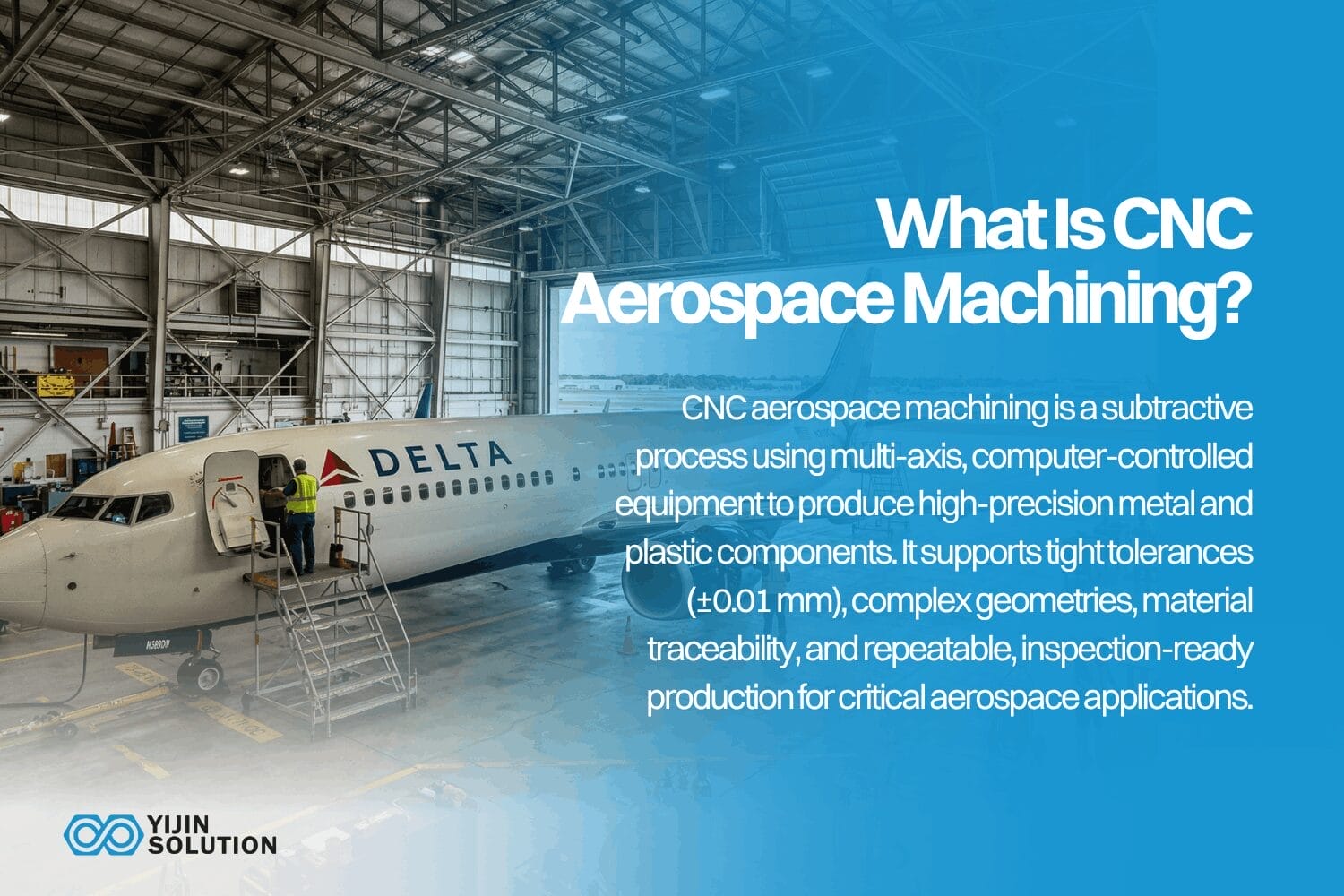
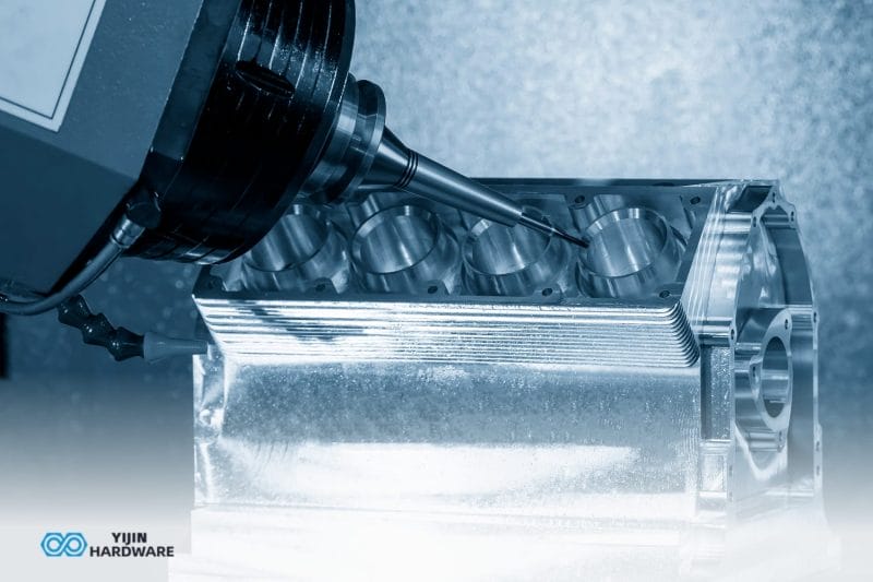
CNC aerospace machining is a subtractive manufacturing process that uses computer-controlled multi-axis cutting equipment to produce flight-ready and flight-adjacent metal and plastic components to precise dimensional specifications.
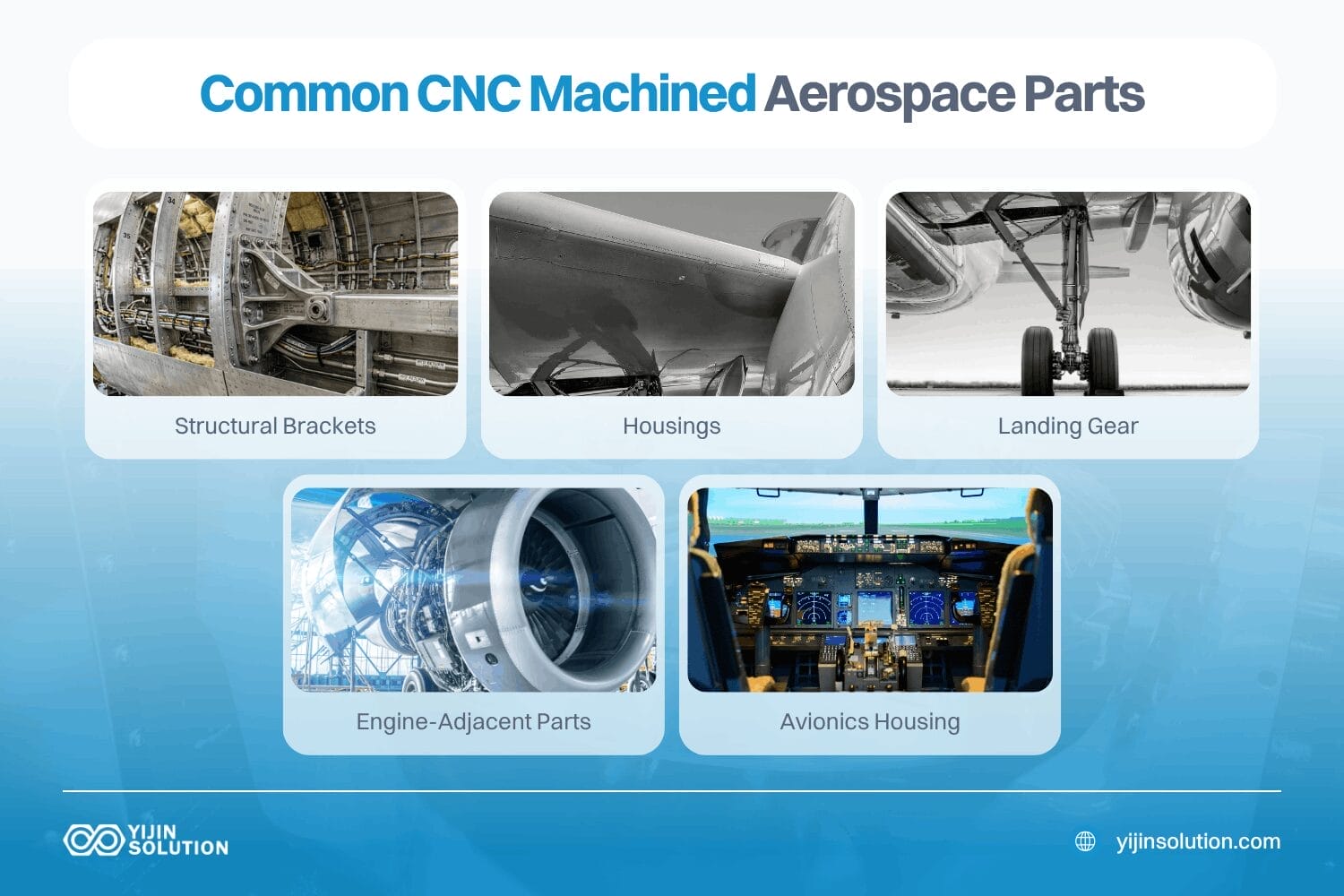
It is used for structural brackets, housings, engine-adjacent parts, and avionics enclosures. Anywhere that tight tolerances, material traceability, and documented inspection are a baseline requirement, the process has to be CNC machining. It can hold tolerances as tight as ±0.01 mm across complex geometries, with full repeatability across production batches.
The Benefits of CNC Machining for Aerospace Manufacturing
A core benefit of Обработка на станках с ЧПУ for aerospace programs is the combination of dimensional accuracy and process control. Beyond that combination, five other characteristics make CNC machining well-suited to aerospace production:
- Tight tolerances on demand: 5-axis machining centers hold ±0.01 mm on precision features without secondary operations on most features.
- Complex geometry in a single setup: 5-axis simultaneous machining reaches compound angles, deep pockets, and contoured surfaces without repositioning the part. That reduces setup-induced error.
- Batch-to-batch repeatability: Programmed tool paths and in-process probing mean part 1 and part 500 measure within the same tolerance band.
- Prototyping and low-to-medium volume production: CNC machining requires no hard tooling. This makes CNC machining a common fit for flight article prototypes, qualification hardware, and production runs from one unit to several thousand.
- Material compatibility: The process handles titanium alloys, aluminum, nickel superalloys, stainless steel, and performance plastics, which is the full material selection that aerospace designers draw from.
Common Challenges in Aerospace CNC Machining
Aerospace machining has a few recurring challenges that shape supplier selection and program planning.
Difficult-to-machine alloys
Titanium and nickel superalloys account for a significant share of aerospace machining work, and both are materially hostile to cutting tools. Titanium’s low thermal conductivity concentrates heat at the cutting edge, while Inconel’s work hardening behavior increases cutting force with each successive pass.
Experienced aerospace machinists address both by using appropriate carbide grades, high-pressure coolant systems, and conservative radial engagement that limits tool deflection. The workaround yields achievable tolerances, but at longer cycle times and higher tool consumption rates. Those will then factor into the production planning and part pricing.
Batch-to-batch consistency
Aerospace programs often require multiple production releases of the same part across a program’s service life. Maintaining dimensional consistency between early production and later builds requires controlled and documented tooling, fixture, and machining program data. There needs to be document-controlled work instructions, retained first article data, and change notification protocols.
The practical risk is that a supplier who loses configuration control between lots introduces dimensional scatter that does not trace back to a specific process change. Investigating and resolving that non-conformance consumes time on both sides. Suppliers with robust version control on CNC programs, fixture drawings, and tooling assemblies can reproduce the original production conditions reliably, even years after the first article was approved.
Setup variation control
Every time a part gets repositioned in a fixture, positional error gets reintroduced. 5-axis machining might reduce how often that happens by completing complex geometries in fewer setups, but multiple setups are unavoidable sometimes.
For multiple setups, the team can consider datum transfer verification using the CMM or on-machine probing. Both options can help confirm that the positional reference is correctly re-established before cutting resumes. However, this would be added to the process overhead.
Complex geometry and accessibility
Aerospace structures increasingly incorporate topology-optimized or organic geometries that evolved from simulation rather than design convention. These features often require simultaneous 5-axis paths to reach all surfaces without gouging adjacent structures.
Programming these tool paths correctly requires both capable CAM software and machinists who understand the physical constraints of cutter reach and spindle clearance.
What Types of Aerospace Parts are Commonly CNC Machined?
The parts most commonly CNC machined for aerospace fall into a handful of categories, each with its own dominant materials and tolerance profile.
Structural brackets and supports
Airframe brackets and attachment fittings carry flight loads between primary structure and secondary systems. They are typically machined from 7075-T6 or 2024-T3 aluminum, with tight positional tolerances on fastener hole patterns to ensure load paths align across the assembly.
Housings and enclosures
Avionics boxes, sensor housings, and actuator enclosures protect electronics and mechanical systems from vibration, moisture, and electromagnetic interference. Complex internal cavities and mating flange faces are machined to close tolerances for reliable sealing and connector alignment.
Компоненты шасси
Trunnion brackets, uplock fittings, and torque links require high strength-to-weight ratios and fatigue resistance under repeated loading. Titanium and high-strength steel are common here, and surface finish on bearing interfaces directly affects service life.
Engine-adjacent parts
Brackets, clamps, and structural members that operate near combustion zones must hold dimensional stability under sustained high temperatures. Inconel and other nickel superalloys are specified for these environments, and machining them to tight tolerances requires rigidly controlled cutting conditions.
Avionics housings
Avionics enclosures are precision-machined from aluminum to achieve thermal management requirements and RF shielding performance. Wall thicknesses and internal channel geometries are tightly controlled because deviations affect both thermal dissipation and electromagnetic compatibility.
Ducts and conduits
Bleed air ducts, hydraulic manifolds, and fluid routing components require consistent wall thickness and precise port positioning. CNC turning and milling produce the bore tolerances and flange interfaces that prevent leakage and maintain system pressure ratings.
UAV and satellite precision parts
Unmanned systems and small satellite platforms drive demand for lightweight, high-stiffness structures. CNC machining supports complex topology-optimized designs in aluminum and carbon fiber reinforced thermoplastics, where tight tolerances maintain mass properties and structural margins.
CNC Machining Processes for Aerospace Parts
Aerospace parts use different CNC processes depending on geometry, tolerance, and production volume.
Фрезерование с ЧПУ
CNC milling suits airframe ribs, structural brackets, avionics housings, and any part requiring flat faces, pockets, slots, and drilled pattern features.
3-axis milling is fine for most prismatic aerospace parts, but 4-axis and 5-axis milling extend reach to angular surfaces and undercuts. The higher axes reduce the number of setups and the positional error each additional fixturing introduces.
Airframe primary structures particularly benefit from multi-axis milling. They require tight flatness and parallelism tolerances, and multi-axis milling in a single fixture setup delivers better dimensional consistency than sequential 3-axis operations.
Токарная обработка с ЧПУ
Turning produces the rotational components, such as shafts, bushings, cylindrical housings, and threaded fittings, that appear throughout hydraulic systems, engine mounts, and actuator assemblies.
CNC turning centers with live tooling combine turning and milling operations in a single setup. The configuration preserves concentricity between turned diameters and milled cross-features. If your team needs more concentricity tolerances on bearing journals and mating shaft diameters, they can utilize modern turning center controls and in-process gauging.
5-осевая обработка
5-axis simultaneous machining is the capability most associated with aerospace CNC work. It addresses the core challenge of aerospace part geometry: complex multi-face features that cannot be reached from three orthogonal directions.
Impeller blades, turbine shrouds, complex brackets with angled interfaces, and structural fittings with compound mounting faces all require simultaneous 5-axis motion to produce in a single setup.
The fewer setups 5-axis machining provides also mean fewer datum changes. That directly reduces geometric error in the finished part.
EDM and secondary precision processes
Electrical Discharge Machining removes material using controlled electrical discharge rather than cutting force. It is used for hard aerospace alloys where tool pressure would distort thin features. The fine internal slots in turbine components and cooling holes in high-temperature hardware also use the process. Conventional drilling cannot reach these internal geometries.
CNC Machining Capability vs. Aerospace Part Requirements
The table below maps Процесс обработки с ЧПУ capabilities directly against the specifications aerospace procurement teams work with.
| Фактор | Обработка с ЧПУ | Aerospace Requirement |
|---|---|---|
| Typical tolerance | ±0.01 mm precision; ±0.05 mm standard | ±0.01 to ±0.05 mm depending on feature criticality |
| Отделка поверхности | Ra от 0,4 до 3,2 мкм | Ra 0.8 to 1.6 µm typical; polished for fatigue-critical zones |
| Compatible materials | Titanium, aluminum, Inconel, stainless steel, engineering plastics | AS7475, 7075-T6, Ti-6Al-4V, Inconel 718, PEEK |
| Lead time | 10 to 15 days production; 7 days expedited for mini orders | Prototypes are often needed in ≤10 days to maintain schedule |
| Max part size | Up to 3,000 mm long | Covers most structural brackets, housings, and frames |
| Axis capability | 3-axis, 4-axis, 5-axis, Swiss turning | 5-axis required for complex geometries and reduced setups |
| Quality standard | AS9100D certified | Mandatory for flight-ready and flight-adjacent components |
| Документация | Material certs, CMM reports, FAIR, PPAP Level 3 | Full traceability required from raw stock to shipped part |
| Inspection equipment | Zeiss CMMs, image measuring systems, 281 sets of testing instruments | Dimensional verification and feature-by-feature validation |
Key Materials for Aerospace CNC Machining
Aerospace parts face thermal cycling, mechanical fatigue, and chemical exposure throughout their service life, which is why material selection carries as much weight as geometry.
Four material groups account for the majority of aerospace CNC machining work.
Titanium alloys: Ti-6Al-4V
Ti-6Al-4V is the most widely used titanium alloy in aerospace. It delivers about 950 MPa tensile strength at a density of 4.43 g/cm³, which is why it appears on structural parts, engine supports, and joints where weight reduction matters. The alloy also resists corrosion in salt spray and hydraulic fluid environments without an added protective coating.
Titanium is harder to machine than aluminum or stainless steel. Its low thermal conductivity concentrates heat at the cutting edge, which drives tool wear and can degrade the surface finish when the process is not tightly controlled.
Stable fixturing, conservative cutting parameters, and high-pressure coolant are the practical response. Toolpath control helps hold dimensional accuracy on critical surfaces where heat buildup would otherwise drift features.
High-strength aluminum: 7075-T6 and 6061-T6
7075-T6 is the common aerospace aluminum for high-load applications. Its tensile strength of about 572 MPa suits airframe ribs, wing spars, and brackets where both weight and strength matter. It also performs well under repeated loading, which is why it appears on flight components subjected to fatigue.
6061-T6 has lower strength at about 310 MPa, but machines more easily and accepts welding and anodizing. It is commonly specified for housings, enclosures, and secondary structural parts where the higher strength of 7075 is not required.
Inconel and high-temperature superalloys
Inconel 718 holds its strength at temperatures above 1200°F, which is why it appears on exhaust systems, combustion hardware, and parts near the turbine section. It also resists oxidation in hot gas environments, so most non-rotating parts need no added surface protection.
Machining Inconel is demanding. It work-hardens quickly, generates high cutting forces, and wears tools faster than aluminum or steel, which stretches cycle time and raises part cost.
Holding tight tolerances on Inconel requires stable cutting parameters, consistent coolant delivery, and tool-wear monitoring. Toolpath strategy matters on critical features, where surface condition and dimensional stability both need to hold through the cut.
High-performance plastics
Aerospace interiors, wire conduit clamps, ducting brackets, and service tray frames use engineering polymers. These areas are where weight reduction and electrical insulation take priority over structural load-carrying. PEEK, PTFE, and Ultem 1010 are common specifications.
PEEK retains mechanical properties above 480°F and passes flame, smoke, and toxicity requirements for cabin applications. Ultem 1010 provides similar FST compliance at a lower material cost.
Machining these materials requires lower cutting speeds than metals and careful chip evacuation to prevent thermal distortion of thin-wall features. Tolerances achievable in CNC-machined PEEK components are tighter than what injection molding delivers without secondary operations, which suits low-volume aerospace interior programs.
Design for Manufacturability in Aerospace CNC
Performance-optimized aerospace geometries are often the hardest to machine because engineering intent and production feasibility do not always align. DFM analysis identifies the features that will drive cost and tolerance risk.
The design parameters below consistently benefit from DFM review before a drawing is released to machining:
Wall thickness consistency
Thin walls and thick sections in the same part create differential stiffness that can cause deflection under cutting forces. Where possible, wall thickness transitions should be gradual. There should also be a confirmed minimum wall thickness against the material and machining strategy before the model gets finalized.
Internal radii
Inside corner radii smaller than the available tooling require specialty cutters and slow, shallow finishing passes. This significantly increases cycle time. DFM can improve this by matching internal radii to standard tool diameters available in the shop.
Deep cavity limits
Depth-to-width ratios above 4:1 on milled pockets limit tool rigidity and increase vibration. From here, surface finish and tolerance hold degrade. Where deep pockets are structurally necessary, DFM can flag them early so the machinist can plan tooling and depth-of-cut strategy.
Tolerance stack-up management
Complex assemblies accumulate dimensional variation across each mating interface. DFM analysis identifies which features drive the most sensitive stack-up chains, ensuring tight tolerances are applied where they matter, not uniformly across every dimension on the drawing.
Balancing lightweighting with machinability
Topology-optimized aerospace structures can produce geometries that are structurally efficient but difficult to fixture and machine consistently. DFM review identifies features where minor geometric modifications maintain the structural intent while restoring machinability and fixture contact reliability.
How to Achieve Tight Aerospace CNC Tolerances
The factors below determine achievable tolerance in practice:
- Machine stability: Thermally stable machine structures reduce thermal drift over a long production run. Spindle warm-up protocols and controlled shop floor temperature contribute meaningfully to held tolerance.
- Fixturing: A workpiece that deflects under cutting forces produces dimensional scatter. Custom fixtures that support thin walls and long overhangs keep the part rigid throughout the cut.
- Tooling condition: Worn tooling introduces dimensional error, and a measurable force increase alerts the operator. Predictive tool life management prevents tolerance exceedance at end-of-life.
- Thermal control: High-pressure through-spindle coolant removes heat from the cutting zone before it conducts into the part. For titanium and Inconel, this isn’t optional. Uncontrolled thermal expansion shifts features by several micrometers between roughing and finishing passes.
- In-process measurement. On-machine probing between operations catches setup drift and confirms feature position before the part leaves the fixture. This avoids scrapping components that have accumulated several hours of machining time.
- 5-axis capability. Reducing part repositions eliminates the accumulated positional error each setup introduces. 5-axis machining centers complete complex geometries in fewer setups, which directly improves geometric consistency across a production batch.
Why Surface Finish Matters for Aerospace Machined Parts
Surface finish requirements in aerospace depend on what that surface actually does in service:
- Airflow-facing surfaces on aerodynamic structures benefit from low roughness to reduce turbulent boundary layer development.
- Sealing surfaces on hydraulic fittings and pressurized enclosures require Ra 1.6 µm or finer to achieve reliable gasket compression.
- Fatigue-sensitive interfaces on landing gear and flight control brackets are often specified at Ra 0.4 to 0.8 µm, then shot-peened to introduce compressive residual stress that slows crack initiation.
Internal pockets, non-functional faces, and weight-reduction cutouts carry no such requirements. Ra 3.2 µm as-machined is the appropriate specification for these features, the natural finish from a sharp end mill at appropriate cutting parameters.
One of the most common DFM errors on aerospace drawings is over-specifying surface finish. There’s likely no need to apply Ra 0.8 µm to every face on a part. It only adds to machining time and cost without improving performance.
Aerospace Certifications, Traceability, and Quality Standards
For aerospace programs, traceability, inspection records, and a certified quality management system get a part released for flight.
The certifications and documentation standards below are the ones aerospace suppliers are typically expected to meet.
AS9100D for process control
AS9100D is the International Aerospace Quality Group’s quality management standard for aviation, space, and defense organizations. It extends the ISO 9001 framework with aerospace-specific requirements covering risk management, configuration control, operational planning, and traceability.
AS9100D compliance drives consistent documentation of setup conditions, tooling changes, and in-process inspection results. It requires that process changes go through a controlled review before the first production part is cut. For procurement teams, an AS9100D-certified supplier provides audit evidence and nonconformance records on request, which feeds into supply chain risk assessments and customer surveillance programs.
Material traceability and inspection documentation
Aerospace quality requirements do not stop at dimensional inspection. Procurement teams need to confirm that the material in a delivered part matches the alloy, temper, and heat or lot number on the engineering drawing. These should be done with an unbroken paper trail from the mill certificate to the shipped part.
Lot-level traceability requirements mean that raw stock must be stored, staged, and issued to production jobs with its identification preserved at every step.
Standard documentation packages for aerospace CNC orders include:
- Material certifications confirming chemistry and mechanical properties to the specified standard.
- CMM inspection reports showing measured values against drawing tolerances.
- First Article Inspection Reports structured to AS9102 for qualification hardware.
For programs requiring PPAP Level 3, the documentation package expands to include process flow diagrams, control plans, and measurement system analysis results.
Inspection equipment and verification
Dimensional verification in aerospace machining requires equipment whose measurement uncertainty is a fraction of the specified tolerance.
Coordinate Measuring Machines measure feature position, form, and orientation with measurement uncertainty well below ±0.001 mm, which provides the margin needed to make reliable conformance decisions at ±0.01 mm tolerances. Image measuring systems verify two-dimensional features such as hole patterns and edge profiles optically, without the contact force that can distort thin-wall components.
Sourcing Custom Aerospace Parts with Yijin Solution
Aerospace part sourcing is as much about traceability, inspection records, and documented process control as it is about machining tolerances.
Yijin Solution supports aerospace projects with AS9100D-certified quality management, 5-осевая обработка с ЧПУ, and in-house CMM inspection, plus the material certifications and First Article Inspection reports that travel with the parts.
For a program with strict tolerance and documentation requirements, get a free CNC quote with a DFM review at the quoting stage.
CNC Machining Aerospace Parts FAQs
What is the typical lead time for custom aerospace CNC parts?
Standard production lead time at Yijin Solution is 10 to 15 days for CNC machined parts, with a minimum order expedited option available at 7 days. Prototype aerospace hardware can often be prioritized within this window.
Parts machined from specialty superalloys such as Inconel 718 may require additional time for specialty tooling procurement and extended in-process verification. Lead time for these materials should be confirmed with our engineering team at the quoting stage.
Can you machine both aerospace plastics and metals?
Yes, you can machine aerospace metals alongside high-performance engineering plastics such as PEEK, Ultem, and PTFE. Dedicated tooling is maintained for plastic machining to prevent cross-contamination between material types. This separation matters for aerospace programs where material identification and traceability requirements extend to tooling contact with certified stock.
What documentation is provided with aerospace CNC orders?
Standard packages include material certifications confirming alloy, temper, and heat lot; CMM inspection reports against drawing tolerances; and First Article Inspection data to AS9102 for qualification hardware. PPAP Level 3 packages are available on request.
What is the minimum order quantity for aerospace CNC parts?
There is no minimum order quantity. Prototypes and qualification hardware are machined on the same equipment, with the same tooling and quality system as production runs. This is so that the first article hardware and low-rate initial production meet the same dimensional and documentation standard as volume orders.
Do you sign NDAs for aerospace projects?
Yes, confidentiality agreements are standard practice for aerospace and defense work, and we sign them before any design files, drawings, or program details are shared. All technical data is handled under strict internal access controls, and our facility does not sub-contract aerospace machining to third parties; your parts are produced entirely within our Shenzhen factory.
Вернуться к началу: CNC Machining Aerospace Parts: Materials, Tolerances, and Standards