
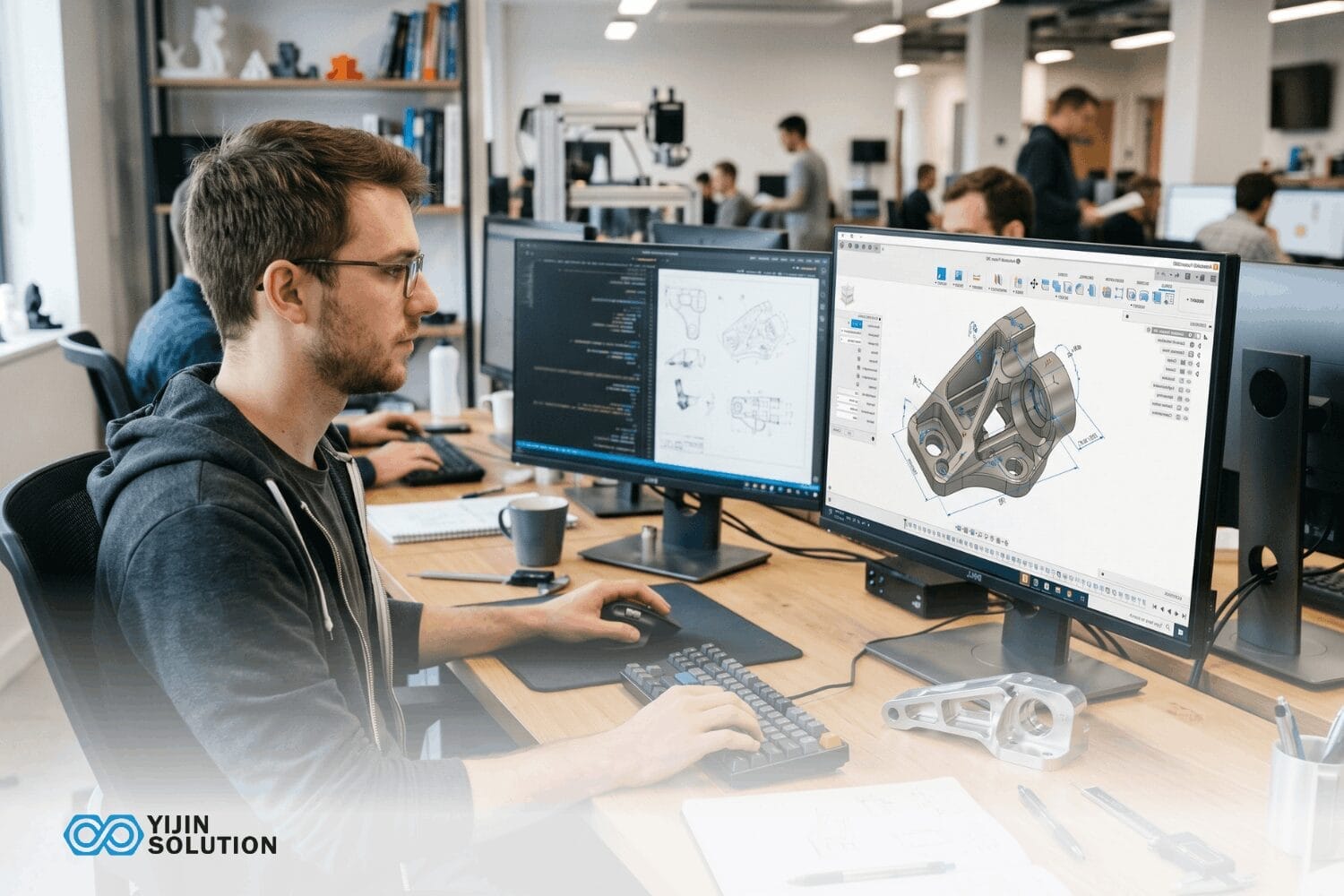
A working prototype on the desk is proof of concept, not proof of manufacturability, even when the geometry fits and the test results look good. The variables that drive production change after a prototype is validated: materials get re-specified for cost and availability, tolerances tighten, and informal test notes turn into formal traceability packages that auditors will scrutinize.
The sections below trace that full transition end to end: the prototyping stages that lead up to it, the process selection logic underneath, and the decisions that separate projects hitting production on schedule from the ones that stall in pilot.
What does Going from Prototype to Production Actually Involve?
Going from prototype to production is the process of converting a validated design into a repeatable, quality-controlled manufacturing operation. It covers design freeze, DFM optimization, process selection, production documentation, pilot batch validation, and full-scale manufacturing ramp-up.
The transition is a structured sequence of decisions, each building on the one before, that turns a one-off proof of concept into a part that can be manufactured consistently at volume.
Prototype vs. Production: At a Glance
The core shift between prototyping and production is the move from a validation tool to a repeatable manufacturing system. The table below captures the key attributes that change across the transition.
| Атрибут | Прототипирование | Производство |
|---|---|---|
| Primary goal | Validate design and function | Manufacture parts reliably at volume |
| Typical quantity | От 1 до 50 единиц | 100 to 100,000+ units |
| Common processes | CNC machining, 3D printing, vacuum casting | CNC machining, injection molding, die casting, sheet metal |
| Допуски | Varies by method; often wider to iterate quickly | Tighter, process-specific; locked to drawing |
| Tooling and setup cost | Low; no hard tooling required | Higher; hard tooling for molding and casting |
| Per-part cost | Higher per unit | Lower at volume once tooling is amortized |
| Время выполнения | 1 to 10 days via rapid prototyping | 7 to 35 days depending on the process and volume |
| Гибкость конструкции | High: changes are inexpensive | Low: design changes after tooling are costly |
| Quality documentation | Informal; test-driven | Formal: PPAP, FAIR, traceability required |
| DFM analysis | Optional but valuable | Required before tooling commitment |
The Stages of Prototyping: From Concept to Production-Intent
A prototype is a physical or functional model built to validate specific aspects of a design before production commitment. Prototypes are not rough first attempts. They are validation tools at different stages of product development, and each stage answers a different question about whether the design is ready to manufacture.
Adequate prototyping before tooling commitment delivers three things: confidence that the design performs under real conditions, confirmation that the part can be manufactured at the target cost, and evidence that the assembly works with mating components.
Concept and proof-of-concept prototypes
These validate the core idea. Does the mechanism work? Are the primary dimensions roughly correct? Common methods include FDM 3D-печать и basic CNC machining. These parts are not production-intent and should not be treated as such. Surfacing manufacturability questions at this stage, even informally, saves significant time later in the development cycle.
Functional prototypes
Functional prototypes test real-world behavior: tolerances, assembly fit, thermal load, and material performance under operating conditions. CNC machining is the preferred method at this stage because it uses production-grade materials at representative tolerances. Vacuum casting works well for batches of 10 to 50 parts needed for initial field testing.
Engineering validation prototypes (EVT)
EVT marks the first time a prototype is built with full production-intent geometry and DFM considerations applied. Teams typically produce 20 to 50 units via CNC or soft tooling. The goal is to confirm that the design will function correctly under intended operating conditions.
Pre-production prototypes: DVT and PVT
DVT (Design Validation Test) verifies that the design can be manufactured consistently at scale using production tooling and processes. PVT (Production Validation Test) validates the production line itself: cycle times, yield rates, and rework frequency. Parts from this stage are often used for regulatory testing and first customer shipments.
The Prototype-to-Production Process: A Step-by-Step Walkthrough
The journey from a validated prototype to full production is a sequence with feedback loops, not a rigid waterfall. Each step produces a specific output that feeds the next decision. Skipping a step means the gaps usually show up downstream as delays, rework, or yield problems.
1. Validate the prototype design and freeze specifications
By this point the prototype works. The remaining task is to lock dimensions, materials, and tolerances into a frozen design package. That package includes full GD&T callouts, target material specifications, and surface finish requirements. Freezing the specification is the gate that opens DFM review and production quoting. Until the design is frozen, no supplier can give a reliable quote, and no tooling investment makes sense.
2. Apply DFM and adjust the design for the production process
Design for Manufacturability (DFM) is the engineering discipline of designing parts so they can be produced cost-effectively, consistently, and at volume. Boothroyd Dewhurst, the originator of the DFMA methodology, estimates that around 70 to 80% of manufacturing cost is locked in during design, which is what makes this step the highest-leverage one in the transition.
DFM at this stage is process-specific. A CNC prototype that will be injection molded in production needs draft angles, uniform wall thickness, and gate placement designed into the geometry. A sheet metal part needs bend radii confirmed with the fabricator and flat-pattern nesting considered for material utilization. The cost of these changes at the design stage is measured in engineering hours; the cost of the same changes after tooling is cut is measured in weeks of lead time and thousands of dollars in rework.
The core DFM considerations break down as follows, each tied to a buyer consequence:
- Wall thickness and minimum features: Walls too thin for the process create short shots in molding and distortion in machining. Excessive variation in wall thickness causes warping and sink marks.
- Draft angles: Without adequate draft, molded and cast parts stick in the tool, causing ejection damage and shortening tool life.
- Tolerance stacking: Individual tolerances may be achievable, but when multiple tolerance features interact in an assembly, cumulative variation can cause fit failures.
- Material and process alignment: The prototype material may not be available or cost-effective in the production process. A CNC-friendly alloy might not be die-castable.
- Assembly sequence and fastener count: Every additional fastener adds assembly labor, and every additional component adds a potential failure point and a line item on the bill of materials.
3. Select the production manufacturing process
Process choice depends on volume, tolerance, geometry, and material. It is the most consequential cost decision after DFM. The dedicated process selection section below provides detailed guidance on when CNC machining, injection molding, die casting, and sheet metal fabrication each become the right choice.
4. Prepare production documentation
Before a supplier can quote production, a complete documentation package needs to be in place. Incomplete documentation is the most common cause of quote delays and the most preventable source of friction in the prototype-to-production handoff.
A complete production documentation package includes:
- 2D engineering drawings with full GD&T callouts
- 3D CAD files in STEP format, preferred for cross-platform compatibility
- Bill of materials (BOM): a structured list of every component, raw material, and quantity required for one assembled unit
- Material specification with grade and condition
- Surface finish requirements
- Target quantity and delivery schedule
- Compliance or certification requirements specific to the target industry
The BOM deserves particular attention. It defines every purchased part, every raw material, and every quantity needed per assembled unit. Errors in the BOM propagate through every stage of production, from quoting through incoming inspection.
5. Run a pilot batch
A pilot run is a structured validation gate, not just “making a few parts.” It validates the production process, the tooling, the quality control procedures, and the supplier’s ability to hold specification consistently. Typical pilot quantities range from 20 to 200 units, depending on complexity and production volume target. The dedicated Pilot Production Runs section below covers what to test and how pilot runs affect pricing.
6. Transition to full production
Once the pilot confirms yield, dimensional conformance, and supplier consistency, full production begins under the agreed quality control protocol. Supplier scorecards covering on-time delivery, defect rate, and response time become the operational metrics that govern the ongoing relationship.
Production Process Selection: Matching Process to Volume and Tolerance
This section answers the question every buyer faces after DFM: which process should the production run use? Each option below pairs a directional recommendation with volume, geometry, material, and tolerance. All tolerance and lead time figures are typical achievable ranges and depend on part geometry, material, and supplier capability.
CNC machining: when it stays the right choice for production
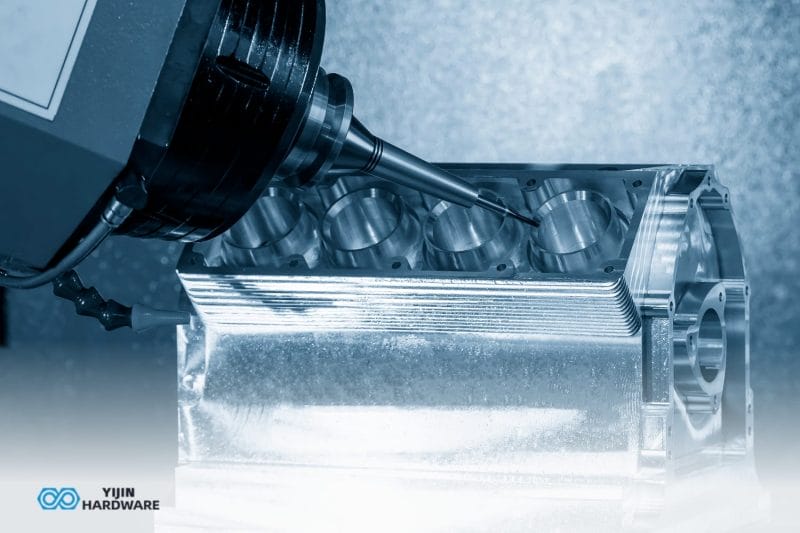
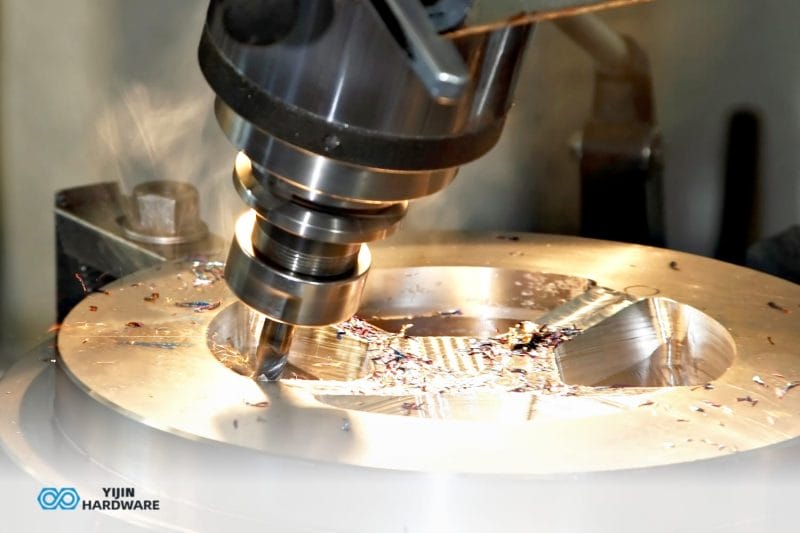
Обработка на станках с ЧПУ stays cost-effective into production volumes when parts require tolerances tighter than 0.05 mm, when geometry is too complex for molds, when annual volumes are under approximately 5,000 units, or when materials such as titanium or Inconel are not castable. Achievable tolerances on well-set-up 3-axis to 5-axis equipment commonly reach 0.01 mm where part geometry and material allow. Typical lead times: samples in around 7 days, bulk production in 10 to 15 days.
Injection molding: when volume justifies tooling
Injection molding becomes cost-effective once volumes exceed roughly 1,000 to 5,000 units per run, the point at which tooling cost amortizes below the per-part savings. Parts must be redesigned for uniform wall thickness, draft angles, and gate placement.
Achievable tolerances are around 0.05 mm where the design and tooling support it. Mold tooling plus first-shot samples typically take 25 to 35 days. Aluminum prototype molds start at $3,000 to $15,000, while multi-cavity hardened steel production molds can exceed $100,000.
Die casting: thin-wall complexity at volume
Литье под давлением suits aluminum, zinc, and magnesium alloy parts at volumes above 5,000 units, particularly thin-wall structures and complex exterior geometries. Standard tolerance is around 0.30 mm; precision features can reach 0.10 mm where design and geometry allow. Tooling plus samples typically run 25 to 35 days. A key DFM requirement: generous draft angles and radii to prevent die wear and ejection defects.
Sheet metal fabrication: structural and enclosure applications
Производство листового металла suits structural brackets, enclosures, panels, and housings where flat blanks, bending, and welding apply. No tooling cost for simple profiles; laser-cut programs start immediately. Achievable tolerances are around 0.10 mm on standard sheet metal work. Prototyping lead time is 3 to 7 days. Production runs 7 to 15 days.
Process selection: quick reference
| Процесс | Ideal Volume | Типичный допуск | Lead Time, Samples | Лучшее для |
|---|---|---|---|---|
| Обработка на станках с ЧПУ | 1 to ~5,000 units | 0.01 to 0.05 mm | Around 7 days | High-precision metal and plastic parts, low-volume runs |
| Листовой металл | 1 to 10,000+ units | 0.10 to 0.30 mm | 3 to 7 days | Enclosures, brackets, structural panels |
| Литье под давлением | 1,000 to 500,000+ units | 0.05 to 0.20 mm | 25 to 35 days | High-volume plastic parts |
| Литье под давлением | 5,000 to 500,000+ units | 0.10 to 0.30 mm | 25 to 35 days | Thin-wall non-ferrous alloy parts at volume |
Disclaimer: Tolerances and lead times shown are typical achievable ranges and depend on part geometry, material, and feature complexity. Confirm against the specific part during quoting.
Pilot Production Runs: Bridging the Gap Before Full Scale
Most articles on the prototype-to-production transition skip this step or underplay it. A pilot run is a structured validation gate that confirms the production process, the tooling, and the supplier’s consistency before committing to a full-scale order.
Typical pilot quantities range from 20 to 200 units, depending on part complexity and production volume target. Pilot runs can be skipped when the geometry is simple and the production process is well characterized. They should not be skipped when new tooling is involved, when tolerances are tight, or when the parts serve a regulated industry such as aerospace or medical devices.
What to test during a pilot run
- Dimensional conformance against final drawing tolerances, measured on a CMM or equivalent equipment
- Assembly yield and fit of mating parts across the full batch, not just a single sample
- Surface finish consistency from the first part to the last, looking for process drift
- Cycle time against target production rate, confirming the quoted throughput is achievable
- Tooling wear after the first production-equivalent shots or setups
- Documentation readiness: confirm that FAI, PPAP, and traceability records are complete and accurate
How pilot runs affect final pricing
Pilot run unit costs are higher than mass production rates because setup costs amortize over fewer parts. This is expected and should be budgeted separately from prototype costs and production unit costs. The pilot is an investment that confirms production readiness; the alternative, discovering process problems at full-scale volume, costs significantly more.
Quality Control from Prototype to Production
Quality control in production is systematized, not ad hoc. During prototyping, inspection is often manual and part by part. At production volume, the quality system shifts to statistical sampling, calibrated measurement equipment, and formal documentation that travels with every shipment. Knowing what to expect and what to ask for puts the buyer in control of incoming quality.
First Article Inspection and PPAP
First Article Inspection (FAI) confirms that the first parts from a production run conform to all drawing requirements before mass production proceeds. PPAP Level 3 documentation is required for automotive supply chains and is commonly requested by aerospace and medical device buyers. Both are buyer-side protections that verify the supplier’s process can produce conforming parts consistently.
Inspection methods at scale
At production volume, inspection scales with the process. Coordinate measuring machines (CMMs) verify dimensional accuracy on critical features. Automated optical sorting catches surface defects and dimensional outliers across large batches. Hardness testing confirms the material heat treatment. Statistical process control (SPC) tracks dimensional trends across production runs to catch drift before it becomes a defect.
Certifications that matter by industry
- AS9100D: required for aerospace component manufacturing
- IATF 16949: covers automotive supply chains
- ISO 13485: governs medical device production
- ISO 9001: quality management baseline that most precision manufacturers hold
Verify that the supplier holds the certifications relevant to the project’s industry before sharing detailed designs. Certifications are the cheapest filter to apply early; once a supplier has been awarded a project, switching for a missing certification costs schedule time.
Common Pitfalls in the Prototype-to-Production Transition
Every team that has taken a product from prototype to production has a list of things they wish they had caught earlier. The pitfalls below are the ones that show up most often, and each is avoidable with straightforward planning.
Building around components that will be obsolete at scale
Specify production-grade components from authorized distributors with published support timelines and counterfeit protection from the start. Hobbyist-grade components sourced through consumer marketplaces work for early prototypes, but they carry no lifecycle guarantees. An electronic component discontinued six months after design freeze can force a board redesign that delays the entire production timeline. Enterprise distributors such as DigiKey and Newark publish end-of-life schedules and offer part traceability.
Ignoring tolerance stack-up
A prototype that fits together when every part sits at nominal dimension may not fit when each part is at the extreme of its tolerance band. Run a stack-up analysis on critical mating dimensions before tooling. This is particularly relevant for assemblies with three or more mating components, where cumulative variation becomes the dominant failure mode.
Substituting materials without re-validating performance
A prototype material chosen for ease of machining may not perform identically once switched to the production material, even within the same alloy family. Thermal conductivity, hardness, and corrosion resistance can vary between grades. Run functional testing on parts produced in the actual production material before locking the design.
Skipping the pilot run
Teams under deadline pressure often treat pilot runs as negotiable. They are negotiable only when the production process is well characterized and the tooling is mature. For new tooling or tight tolerances, a 20 to 200 unit pilot run is the cheapest insurance against full-scale yield problems.
Choosing the Right Manufacturing Process for Production

The right partner removes friction at every stage of the transition. Suppliers should be evaluated against the criteria below, each framed as a capability, why it matters, and what to look for.
Continuity from prototype through production
One facility, one engineering team, and one quality system remove the handoff delays that introduce quality drift between stages.
What to look for: a supplier that quotes prototype and production from the same engineering team, not two separate departments or sister companies.
DFM review at the design stage
Engineering input before tooling commits surface cost and feasibility issues while changes are still inexpensive.
What to look for: a supplier that includes DFM review in the quote rather than charging for it, and that returns specific feedback on geometry and process, not generic checklists.
Prototype turnaround that does not bottleneck design iteration
Sample lead times directly affect how quickly the design can iterate against test results.
What to look for: published sample lead times of under a week for standard materials, with a stated commitment to in-process status updates rather than ship-and-pray scheduling.
Quality systems matched to your industry
Industry-specific certifications are buyer-side protection that a supplier’s quality system has been audited against the standards the project will eventually need.
What to look for: AS9100D for aerospace, IATF 16949 for automotive, ISO 13485 for medical, and a willingness to share certificates on request before any drawings are exchanged.
Take the Next Step with Yijin Solution
The transition from prototype to production is won or lost in the decisions made before tooling locks in, and the supplier choice is the largest of them. Yijin Solution handles CNC machining, sheet metal fabrication, injection molding, and die casting under one quality system. We hold AS9100D, IATF 16949, ISO 13485, and ISO 9001 certifications, with lead times for prototypes in 3 to 7 days and production runs typically in 2 to 4 weeks, depending on project complexity.
Send a CAD file and a target volume for a quote and DFM feedback within 24 hours.
FAQs on Prototype to Production
How long does the full transition from final design to first production shipment take?
The total transition time depends on the production process and the number of pilot iterations. A CNC-based path with no hard tooling can move from design freeze to first production shipment in approximately 4 to 6 weeks. An injection-molded or die-cast path with new tooling typically takes 8 to 12 weeks, including tooling fabrication, first-shot validation, and a pilot run.
Do I need new tooling for production if my prototype is CNC-machined?
If the production process is also CNC machining, no hard tooling is required. The same fixturing approach used for prototypes scales to production volumes. If the production process is injection molding or die casting, a tooling investment is required because the prototype process and production process are physically different. The decision depends on production volume: above roughly 1,000 to 5,000 units, hard tooling typically pays for itself.
How much does it cost to take a prototype to production?
Costs split into three buckets. Prototype costs vary by complexity: typically $100 to $1,000 for simple parts, $1,000 to $10,000 for functional prototypes, and $10,000 or more for production-intent builds. Tooling costs are effectively zero for CNC machining and sheet metal, but ranges from $3,000 to $100,000 or more for injection molding depending on cavities, material, and steel grade. Per-unit production cost then depends on volume. Tooling is justified once per-unit savings outpace the upfront tooling investment, typically at 1,000 or more units for injection molding.
What is a typical minimum order quantity for production?
The minimum order quantity depends on the production process, not the supplier. CNC machining and sheet metal fabrication have effectively no MOQ; orders can start at single units. Injection molding and die casting do not have a strict MOQ either, but per-unit cost only becomes competitive above the volume that justifies the tooling investment: typically 1,000 or more units for injection molding and 5,000 or more for die casting.
How do tolerances change when the production process differs from the prototype process?
When the same process is used for both prototype and production, tolerances stay consistent. When the process changes, such as moving from a CNC prototype to injection-molded production, tolerances, wall thickness requirements, and part geometry usually need adjustment to suit the new process. That adjustment is exactly what DFM analysis addresses before tooling is committed.
Вернуться к началу: From Prototype to Production: A Complete Manufacturing Guide