
CNC sharp inside corners are interior intersections on a milled part: two walls meeting at 90 degrees with no fillet specified. They are one of the most common manufacturability issues in machined parts, because a cylindrical end mill physically cannot reach into a square internal corner. A 6 mm end mill, for example, leaves at least a 3 mm radius in any pocket it cuts.
This guide explains why sharp inside corners happen, what they cost, and how to handle them, from simple design changes to Wire EDM for parts that genuinely need a sharp edge. The aim is to keep the part manufacturable without losing function.
What are Sharp Inside Corners in CNC Machining?
A sharp inside corner is any interior intersection where two walls or surfaces meet at 90 degrees, or close to it, with no fillet or radius specified. On a drawing, it looks like a clean right angle. In a manufactured part, it almost never is.
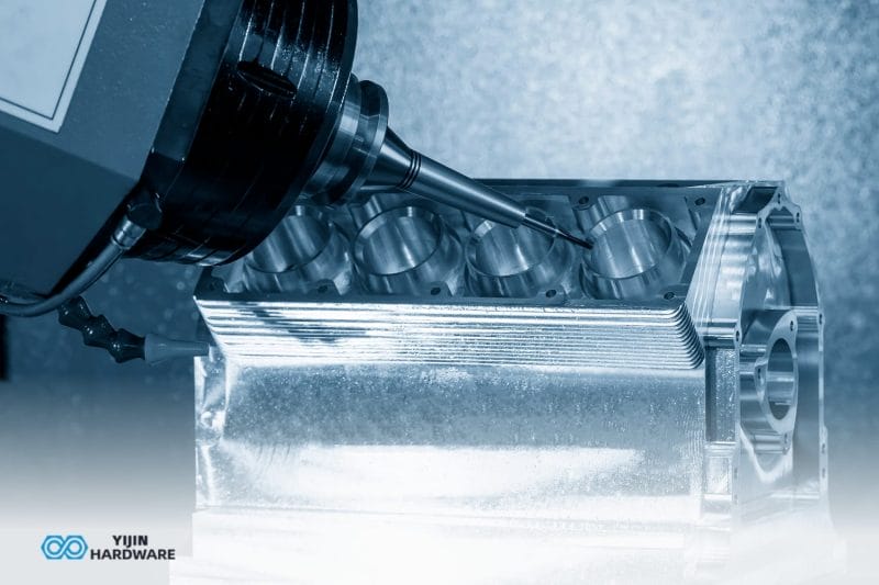
External corners behave differently. A rotating end mill can trace the outside edge of a block and leave a crisp external corner without difficulty, since the tool simply profiles around the outside geometry. Internal corners are the opposite case. When a cylindrical cutter moves into a pocket or slot, its own diameter prevents it from reaching into a square corner.
The reason is that Фрезерование с ЧПУ uses a rotating cylindrical tool to remove material. When that tool cuts along one wall and changes direction to cut along an adjacent wall, it sweeps through an arc at the corner. The minimum radius of that arc equals half the tool’s diameter. A 6 mm end mill leaves a minimum 3 mm radius. A 10 mm end mill leaves a minimum 5 mm radius. Smaller tools produce tighter corners, but the relationship never reaches zero.
Why Sharp Inside Corners are a Problem in CNC-Machined Parts
Getting corner geometry right affects fit, function, and cost across a part’s entire service life. When inside corners are specified correctly, toolpaths run smoothly, cycle times stay predictable, and the part assembles as intended. Specified incorrectly, they push up cycle time, tooling cost, and rework risk.
- Machinability constraints. As a cutter enters a tight internal corner, it engages more material on the inner arc. This increased tool engagement generates higher cutting forces and can cause tool deflection, especially with smaller end mills at depth. Feed rates drop. In deep, narrow pockets with tight corners, the programmer may need multiple passes with progressively smaller tools to approach the specified geometry.
- Cost and lead time. Tight inside corners add cost in several ways. Smaller tools run slower. Multiple tool changes add cycle time. In some cases, a secondary process such as Wire EDM becomes necessary. A pocket that machines in one operation with a generous corner radius may require three operations when the drawing calls for near-sharp corners.
- Functional fit. This is where it matters most. If a square insert, bearing block, or mating bracket needs to seat flush against two walls, even a small residual radius at the inside corner prevents full contact. The mating part either will not assemble, or it rocks on the radius and creates an unstable joint. Assembly interference from unplanned inside radii is one of the most common reasons parts come back from the shop floor for review.
- Quality risk. Pushing very small tools into tight inside corners in harder materials (stainless steel, титан, tool steels) increases tool breakage risk. A broken tool mid-cut can scrap the part and damage the fixture. The risk rises as the length-to-diameter ratio increases.
Some of these problems are unintentional. Imported CAD models often default to sharp edges. Legacy drawings get carried forward without review. Designers working on aesthetics sometimes specify sharp inside corners without realizing the machining implication. A quick DFM check before quoting catches most of these cases.
What is the Sharp Corner Rule?
The sharp corner rule in Обработка на станках с ЧПУ is a design guideline: internal corner radii should match or exceed the radius of the cutting tool being used, and the radius should be specified explicitly on the drawing rather than left as “sharp” or undefined.
The practical implication is that every internal corner in a CNC-milled pocket or slot will have some radius. The designer’s job is to specify one the part can still function with, so the machinist does not have to guess.
A useful starting point is to specify a corner radius equal to at least 1.5 times the tool radius. For a 6 mm end mill with a 3 mm radius, that means specifying at least a 4.5 mm corner radius. This clearance reduces the percentage of tool engagement at the corner, improves обработка поверхности, extends tool life, and keeps machining time down.
Deeper pockets may require larger radii. As pocket depth increases relative to tool diameter, the tool’s rigidity decreases. A corner radius that works at 5 mm depth may cause chatter and tool deflection at 25 mm depth with the same tool. The radius should scale with the feature, not sit at a fixed value regardless of geometry.
What Corner Radii are Actually Achievable in Обработка с ЧПУ?
The table below shows the approximate minimum inside corner radii for different tool diameters. These are indicative ranges based on standard tooling, not fixed rules that apply to every project. Actual capability depends on material, pocket depth, length-to-diameter ratio, and machine setup.
| Tool diameter | Min. inside corner radius | Typical application | Примечания |
|---|---|---|---|
| 2 mm | 1.0 to 1.5 mm | Fine detail features, shallow pockets | Low L/D required; limited depth |
| 4 to 6 mm | 2 to 3 mm | General pockets, slots | Most common range in production work |
| 8 to 12 mm | 4 to 6 mm | Deeper pockets, structural features | Larger tools offer better rigidity and faster feeds |
Several factors push the achievable radius larger or smaller than the tool radius alone suggests.
- Tool length-to-diameter ratio. An L/D above 4:1 increases deflection and chatter risk. Deeper features need either a larger corner radius or a more rigid tool, often both.
- Material hardness. Aluminum is forgiving. Stainless steel and titanium are not. Harder materials require more rigid setups, which usually means a larger tool and a larger corner radius.
- Pocket geometry. A through-pocket allows chip evacuation and coolant flow from both sides. A blind pocket traps chips and heat at the bottom, especially in corners. Blind pockets with tight inside radii are among the most expensive CNC features to machine reliably.
Tighter radii require smaller tools, which run slower, deflect more, and wear faster. Every step down in tool diameter increases machining time and cost. Specifying the largest radius the design can tolerate is almost always the right call.
How to Handle Sharp Inside Corners in CNC-Machined Parts

Most parts do not need every inside corner to be sharp. The approaches below work together as a system. A single part might use generous radii on non-functional pockets, a dog bone relief where a bracket seats, and Wire EDM on one critical keyway. The right combination depends on the part’s function, not on a single rule.
Specify a corner radius in the design
This is the simplest and most cost-effective approach. Add a fillet or corner radius to inside corners that matches available tooling, rather than leaving the corner undefined or marked as “sharp.”
A corner radius equal to at least 1.5 times the tool radius reduces tool engagement at the corner, improves surface finish, and extends tool life. A 4 mm fillet on a non-functional pocket wall costs almost nothing to machine. Leaving that same corner “sharp” triggers either a specialized toolpath with a smaller cutter or a secondary operation, both of which add time and money.
The design question is worth asking early: does this corner need to be tight for functional reasons, or is it just the CAD default? Most of the time, it is the default. A five-minute review of the CAD model before submitting for a quote catches sharp edges on imported geometry that designers commonly miss, and saves days at the back end.
Use a corner relief or undercut
When a corner needs to be tighter than standard tooling allows, typically when a square insert, key, or block must seat flush against two walls, a corner relief solves the problem without requiring a true sharp corner across the full surface.
A dog bone relief, sometimes called a bone fillet, adds a small circular pocket at each inside corner. The pocket diameter is larger than the tool radius, which lets the cutter fully clean out the corner geometry. The mating part seats against the flat surfaces, with the relief providing clearance at the intersection.
T-slot and undercut reliefs work on a similar principle: material is removed at the corner so that the mating component fits. The cost impact is minimal, just one additional toolpath per corner with no secondary process required. Compared to Wire EDM or sinker EDM, corner reliefs save both lead time and budget.
Dog bone reliefs are visible on the finished part. For cosmetic applications, this may matter. For structural assemblies, tooling fixtures, and internal pockets, it is rarely a concern.
Use a smaller cutting tool
A smaller end mill produces a smaller corner radius. This is sometimes the right answer when the inside corner radius must be tight and the part design cannot be changed, for example on a legacy part or a design frozen for production.
The trade-off is real. Smaller tools run at lower feed rates, are more susceptible to deflection, and have a higher breakage risk in harder materials. A 2 mm end mill in Stainless Steel 316 does not behave like a 2 mm end mill in Aluminum 6061. The stainless demands lower surface speeds, lighter chip loads, and shorter passes.
Tools below 3 mm diameter are typically reserved for shallow features with low length-to-diameter ratios. A 2 mm tool driven 15 mm deep into hardened tool steel will break before the cut completes, and the part is likely to be scrapped.
Cost impact: smaller tools increase both machining time and tooling cost, particularly in harder materials. The approach works for shallow pockets and fine detail, but it is a last resort for deep features.
Apply Wire EDM for true sharp internal corners
Wire Electrical Discharge Machining, or Wire EDM, is the standard process for producing near-sharp inside corners. The wire electrode follows the programmed path and cuts using electrical erosion, not mechanical contact, so the achievable radius is constrained by the wire diameter and spark gap rather than by cutter geometry.
A 0.25 mm wire produces an internal corner radius of roughly 0.13 mm. A 0.10 mm wire gets down to approximately 0.06 mm. That is close enough to “sharp” for nearly any engineering application, including punch and die tooling, precision keyways, and tight-tolerance through-pockets when a mating part demands a near-zero corner.
Wire EDM has constraints. It cuts through-features only, so blind pockets are out. Each feature needs a pre-drilled start hole for the wire to thread through. And the process is slower and more expensive per part than standard CNC milling.
Wire EDM makes sense when the inside corner must be genuinely sharp for functional reasons and cannot be solved with a corner relief or a minor design change. For non-functional inside corners, it adds cost without adding value.
Combine CNC machining with secondary operations
Most parts that arrive with “sharp inside corners” on the drawing only need a few of those corners to be truly sharp. The rest are cosmetic or non-functional.
A hybrid workflow handles this efficiently. DFM review identifies which inside corners are functionally critical. Standard CNC milling machines the bulk of the part’s features. Wire EDM, sinker EDM, or specialist tooling is applied only to the corners that require it.
This approach keeps per-part cost under control because the expensive secondary process is limited to the features that actually need it. The rest of the part machines at standard cycle times with standard tooling, available across our Услуги по обработке на станках с ЧПУ.
The DFM review step is what makes this work. Without it, the shop either quotes the entire part as if every corner needs EDM, which inflates cost, or machines it all conventionally and ships corners that do not meet spec.
Decide Each Corner Once, at the Drawing Stage
Choosing between a corner radius, a corner relief, a smaller tool, or Wire EDM is a process routing question, and the most efficient time to answer it is before machining begins.
Yijin Solution’s 136+ CNC machining centers cover 3-, 4-, and 5-axis work for the milling-side approaches, with Wire EDM available for the corners that genuinely need to be sharp. Each corner is routed individually during the DFM review, so blanket EDM doesn’t end up in the quote.
Share your part drawing to get the corner-by-corner routing called out before quoting.
CNC Sharp Inside Corners FAQs
The questions below cover the most common buyer questions about specifying and machining inside corners.
Can CNC machining produce sharp internal corners?
CNC machining cannot produce a true sharp inside corner with standard end mills. The tool geometry always leaves a radius equal to at least half the cutter’s diameter. True sharp internal corners require Wire EDM, sinker EDM, or a corner relief feature in the design. For most applications, specifying a corner radius that accommodates standard tooling is the more practical and cost-effective approach.
What is the minimum inside corner radius I can specify for CNC machining?
The minimum inside corner radius depends on the smallest tool your fabricator can run for that feature, typically between 0.5 mm and 3 mm for most production applications. Pocket depth and material hardness both influence what is achievable. A 2 mm end mill can produce a 1 mm radius in shallow Aluminum 6061, but the same radius at depth in stainless steel may not be practical. A DFM review is the right way to confirm what is achievable for a specific part.
What is a dog bone relief, and when should I use it?
A dog bone relief is a circular cutout added at an inside corner, larger than the tool radius, that allows the cutter to fully clear the corner and leaves the mating surface free of interference. It is the standard solution when a square insert, key, or block must seat flush against two walls. The relief adds minimal machining time and avoids the need for secondary processes such as Wire EDM.
Is Wire EDM always required for sharp inside corners?
No. Wire EDM is only justified when a truly sharp corner is functionally required and cannot be solved through a design change. For most applications, a corner radius or dog bone relief is the right approach and costs significantly less. Wire EDM adds lead time and cost, and should be reserved for features that genuinely demand a near-zero radius.
How do inside corner radii affect machining cost?
Tighter inside corner radii require smaller tools, slower feed rates, and sometimes additional setups or secondary processes. Each step down in tool diameter increases both machining time and tooling cost. Specifying the largest inside corner radius the design can tolerate is one of the simplest ways to reduce per-part cost without changing part function.
Вернуться к началу: Острые внутренние углы ЧПУ: Что это такое, почему это проблема и как с ней справиться