


Un devis de fraisage CNC peut grimper vite lorsque des caractéristiques critiques apparaissent tard dans l'analyse, car les poches profondes, les parois minces, les alésages serrés et les finitions esthétiques modifient chacun le plan de fabrication.
Une sous-traitance en fraisage CNC efficace évalue ces exigences avant de commencer la programmation, plutôt que de simplement prouver qu'une machine peut usiner la géométrie.
Le fournisseur doit déterminer le maintien en position adapté, l'accès des outils, le nombre de montages, le comportement de la matière et les méthodes de contrôle, et ces décisions influent sur le coût, le délai et la régularité dimensionnelle.
Une revue pratique commence par la famille de pièces et ses caractéristiques fonctionnelles, puis définit des tolérances réalistes, sélectionne une matière adaptée et prépare les informations pour le devis.
Qu'est-ce que le fraisage CNC ?
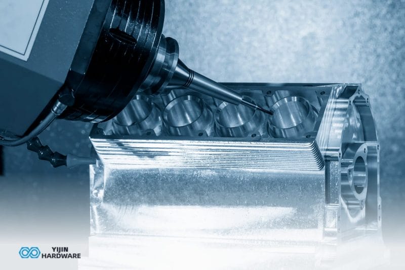
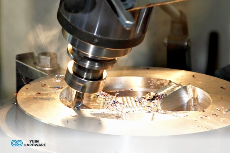
Le fraisage CNC est un procédé soustractif qui enlève de la matière avec des outils coupants rotatifs pilotés par ordinateur. La pièce reste bridée pendant que les trajectoires d’outil programmées créent faces, poches, rainures, trous, filetages et contours. Les tables rotatives peuvent repositionner la pièce en usinage multi-axes.
Comment fonctionne le procédé de fraisage CNC
Le processus commence par un modèle 3D et un plan 2D coté. Les ingénieurs étudient la géométrie, les matières, les tolérances, les finitions et les exigences de contrôle avant la programmation.
La programmation FAO définit les outils, les trajectoires de coupe, les vitesses, les avances, l'utilisation du liquide de coupe et l'ordre des ébauches et finitions.
La pièce est ensuite maintenue par un étau, un montage, un mandrin, un plateau à vide ou un système de maintien sur mesure. Un maintien stable limite les mouvements tout en laissant l'accès aux formes requises.
L’ébauche enlève la majeure partie de l’excédent de matière. Les passes de finition établissent ensuite les dimensions finales, les relations géométriques et l’état de surface.
La pièce terminée passe par l'ébavurage, le nettoyage, le traitement de surface et le contrôle selon les besoins. Services d'usinage CNC peut combiner fraisage, tournage, rectification, EDM et traitement de finition secondaire.
Le fraisage convient généralement aux composants prismatiques avec des faces usinées et des formes internes. Le tournage convient généralement aux composants dont la géométrie principale est de révolution.
Quelles pièces conviennent au fraisage CNC ?
Le fraisage CNC convient aux composants construits autour de faces planes, de poches, de rainures, de bossages, de motifs de trous et de surfaces profilées. Les meilleurs candidats offrent un accès pratique aux outils et des zones de bridage stables.
Familles courantes de pièces fraisées
Les boîtiers et les enveloppes comportent souvent des poches, des bossages de fixation, des ouvertures de connecteurs et des faces d'étanchéité. Les cavités profondes et les fonds minces peuvent augmenter la portée d'outil et les risques de déformation.
Les équerres et les platines de fixation combinent souvent des faces planes, des épaulements, des rainures et des trous de positionnement. La planéité et la position des trous comptent souvent plus que la complexité visuelle.
Les collecteurs comportent des orifices, des passages qui se croisent, des filetages et des surfaces d'étanchéité. Leur plan de fabrication doit prendre en compte les bavures internes, la propreté des passages et les relations entre plusieurs orientations.
Les montages et les plaques d'outillage reposent sur des motifs de perçage répétables, des positions de goupilles et des faces de référence. Les relations de position peuvent avoir une importance fonctionnelle supérieure à la longueur ou à la largeur hors tout.
Quand un autre procédé convient à la géométrie
Les composants de révolution peuvent nécessiter un tournage CNC plutôt qu'un fraisage. Les tôles minces peuvent convenir à la tôlerie, surtout lorsque le pliage peut remplacer un enlèvement de matière important.
L'usinage par électroérosion à fil peut réaliser des rainures étroites, de petits rayons internes et des formes précises dans les matériaux conducteurs. Le procédé est particulièrement pertinent après traitement thermique ou lorsque les efforts de coupe sont indésirables.
Quelles tolérances le fraisage CNC peut-il tenir ?
La tolérance en fraisage CNC dépend de la forme contrôlée, de la matière, de la dimension, de l'accessibilité de l'outil, du maintien de la pièce, du nombre de montages, de la température et de la méthode de contrôle. Un seul chiffre ne peut pas décrire toutes les formes d'une pièce.
Un alésage de précision ne se comporte pas comme une face large ou une paroi mince. Le plan doit imposer des tolérances plus serrées uniquement là où la fonction, l'ajustement, l'étanchéité, l'alignement ou le mouvement l'exigent.
Les valeurs suivantes sont des points de départ pratiques pour votre demande de devis. Tout engagement final nécessite l’étude de votre plan et un processus d’usinage adapté à chaque caractéristique.
| Type de caractéristique | Point de départ indicatif | Conditions qui l'influencent | Vérification type |
|---|---|---|---|
| Dimensions linéaires générales | ±0,05 mm pour des caractéristiques métalliques stables et accessibles | Taille de la pièce, matière, rigidité de paroi, état de la matière et changements de réglage | Pied à coulisse, micromètre ou MMT |
| Alésages et ajustements de précision | ±0,01 à ±0,02 mm après finition contrôlée | Profondeur d'alésage, diamètre, accès outil, température et état de surface | Jauge d'alésage ou MMT |
| Position des trous | 0,05 mm peut être réalisable en un seul réglage maîtrisé | Qualité des références, taille de la pièce, profondeur des formes et répétabilité du montage | CMM |
| Planéité et parallélisme | De 0,05 à 0,10 mm sur 100 mm pour les pièces rigides | Portée, épaisseur de section, contraintes résiduelles, bridage et enlèvement de matière | Marbre ou MMT |
| Parois minces et poches profondes | Analyse spécifique au plan requise | Hauteur de paroi, épaisseur, rigidité de la matière, portée de l'outil, chaleur et pression de bridage | Micromètre ou MMT |
| État de surface usiné | Ra 0,8 à 3,2 µm sur les surfaces accessibles | Matière, géométrie de l'outil, trajectoire d'outil, données de coupe et exigences esthétiques | Profilomètre et standard visuel |
Comment les plans doivent communiquer la tolérance
ISO 2768 fournit un cadre pour les tolérances générales sur les dimensions linéaires et angulaires sans indications de tolérance individuelles. Le plan doit toutefois identifier la classe applicable et tout contrôle plus serré sur une caractéristique.
L'ISO indique la nouvelle édition comme en cours de publication au moment de la rédaction. Les détenteurs de plans doivent confirmer l'édition requise avant de diffuser les données de production.
Les formes critiques nécessitent des contrôles individuels reliés à un schéma de référence fonctionnel. Citons notamment le diamètre d'alésage, la position réelle, la planéité, le parallélisme et la rugosité des faces d'étanchéité.
L'utilisation généralisée de tolérances serrées augmente les passes de finition et les efforts d'inspection. Elle peut aussi réduire la fenêtre de processus sans améliorer la fonction de la pièce.
Comment le contrôle appuie l'engagement de tolérance
Une tolérance devient exploitable pour l’approvisionnement lorsque le fournisseur et l’acheteur s’accordent sur la méthode de mesure. L’échantillonnage, le reporting, la température et les règles d’acceptation doivent aussi être définis.
Les Norme ASME B89.7.2 de planification des mesures dimensionnelles explique pourquoi un plan de mesure approuvé est important. L'incertitude de mesure doit être adaptée à la tolérance et aux conséquences économiques de la décision.
Solution Yijin utilise le contrôle tridimensionnel Zeiss pour les vérifications dimensionnelles et de position définies sur le plan. Sa capacité CNC publiée est une tolérance standard de ±0,05 mm et une tolérance de précision de ±0,01 mm dans des conditions appropriées.
Comment les ingénieurs choisissent-ils une matière pour le fraisage CNC ?
Le choix de la matière commence par les exigences d'utilisation plutôt que par la seule vitesse d'usinage. La résistance, la rigidité, l'exposition à la corrosion, la température, l'usure, le poids, le comportement électrique et les exigences de finition déterminent la présélection.
L'usure des outils, la vitesse de coupe, la disponibilité de la matière, la déformation, le contrôle et la finition peuvent modifier le prix total de la pièce.
ISO 513 classe les matériaux de coupe durs selon leurs applications d'usinage. Ses groupes aident les ingénieurs à relier le comportement de la pièce à la nuance d'outil et à la planification du procédé.
Les inox austénitiques appartiennent au groupe M. L'aluminium, les alliages de cuivre et de nombreux plastiques appartiennent au groupe N.
Ces classifications expliquent pourquoi une seule stratégie d'outil ne peut pas couvrir toutes les familles de matériaux. Chaque groupe crée un équilibre différent entre chaleur, adhérence, effort de coupe et usure de l'outil.
| Matériau | Utilisations courantes | Motif de sélection | Principal compromis |
|---|---|---|---|
| Aluminium 6061 | Boîtiers, supports, plaques et montages | Disponibilité large, résistance modérée, densité plus faible, usinabilité et réponse à l'anodisation | Résistance inférieure au 7075 et déformation possible après un enlèvement de matière important |
| Aluminium 7075 | Supports chargés, composants structurels et montages de précision | Résistance supérieure aux alliages 6xxx courants pour une densité relativement faible | Coût matière plus élevé et aptitude au soudage réduite |
| Inox 303 | Raccords, fixations, arbres et composants filetés | Usinabilité améliorée au sein de la famille 300 | Les exigences de corrosion et de soudage nécessitent une comparaison avec le 304 ou le 316 |
| Inox 304 ou 316 | Équipements pour fluides, matériel médical et pièces exposées à la corrosion | Résistance à la corrosion, durabilité et large disponibilité | Écrouissage, efforts de coupe, usure des outils et temps de cycle plus long |
| Laiton C36000 | Raccords, connecteurs, vannes et matériel électrique | Usinabilité élevée, usinage net des formes, conductivité et résistance à la corrosion | Densité, coût de la matière et exigences en plomb |
| POM ou acétal | Douilles, guides et composants à faible frottement | Stabilité dimensionnelle, faible frottement et comportement d'usinage prévisible | Température, fluage et charge permanente nécessitent une vérification |
| Nylon | Galets, entretoises et pièces d'usure | Ténacité, comportement à l'usure, amortissement et faible poids des composants | L'absorption d'humidité et la flexibilité peuvent modifier les dimensions finies |
| PEEK | Composants haute température, exposés aux produits chimiques, médicaux et électriques | Résistance à la température, résistance chimique, rigidité et faible poids | Coût de la matière, disponibilité des nuances et exigences documentaires |
Aluminium pour les boîtiers, les équerres et les montages
L'aluminium 6061 offre un bon équilibre entre disponibilité, usinabilité, résistance modérée et flexibilité de finition. L'aluminium 7075 offre une résistance supérieure, mais entraîne un coût de matière plus élevé et un comportement à la corrosion différent.
Les pièces en aluminium minces peuvent se déformer à mesure que les contraintes internes se libèrent. Un enlèvement de matière équilibré et des passes de finition planifiées peuvent améliorer la cohérence dimensionnelle.
Inox pour la corrosion et la durabilité
L'inox 303 permet un usinage efficace des raccords, des arbres et des composants filetés. Les nuances 304 et 316 répondent à des applications plus larges sensibles à la corrosion, mais peuvent nécessiter plus de temps d'usinage.
Laiton pour pièces détaillées et conductrices
Le laiton C36000 permet de réaliser des filetages détaillés, des raccords, des connecteurs et des composants de robinetterie. La densité, le coût de l'alliage et les restrictions liées à la teneur en plomb nécessitent toutefois une étude au cas par cas.
Plastiques techniques pour l'allègement et les environnements spécifiques
Le POM convient aux composants à faible frottement, tandis que le nylon apporte ténacité et résistance à l'usure. L'humidité peut influencer la stabilité dimensionnelle du nylon.
Le PEEK convient aux environnements à température élevée et aux environnements chimiques. Le prix de la matière et les exigences documentaires peuvent dominer le devis.
Guide des plastiques usinables met l'accent sur les différences de rigidité, de formation de bavures, de déformation et de contraintes internes. Ces comportements exigent des stratégies de maintien et de coupe propres à chaque matière.
Fraisage CNC 3 axes ou 5 axes ?
Le nombre d'axes doit suivre l'accès aux caractéristiques, la géométrie de surface, le nombre d'orientations et les besoins de maintien en position. Plus d'axes ne signifie pas automatiquement un prix plus bas ou une tolérance plus serrée.
Une fraiseuse 3 axes se déplace selon X, Y et Z. Un système 5 axes ajoute deux mouvements rotatifs qui orientent l'outil ou la pièce.
| Géométrie de la pièce | Position 3 axes | Position 5 axes | Décision pratique |
|---|---|---|---|
| Tôles et équerres avec une face à caractéristique principale | Généralement efficace | Un mouvement supplémentaire peut apporter un gain limité | Utiliser 3 axes sauf si des formes latérales modifient le plan de montage |
| Carters ouverts avec poches accessibles | Adapté à une ou plusieurs mises en position | Utile lorsque plusieurs faces extérieures nécessitent un usinage | Comparez le nombre de montages, les transferts de références et le contrôle |
| Collecteurs avec orifices sur plusieurs orientations | Plusieurs montages peuvent être nécessaires | Le positionnement indexé permet de conserver plus de formes en un seul montage | Envisager le 5 axes lorsque les relations entre perçages le justifient |
| Faces à angle composé | Des montages inclinés peuvent être nécessaires | L'indexation rotative améliore l'accès direct à l'outil | Laissez la géométrie et la répétabilité guider le choix |
| Surfaces à profil continu | Limité par l'orientation et l'accès des outils | Le mouvement simultané maintient l'orientation de l'outil | Envisager le 5 axes pour une découpe continue multidirectionnelle |
Quand le 3 axes est le bon choix
Le fraisage 3 axes convient souvent aux plaques, aux équerres, aux poches ouvertes et aux motifs de perçage standard. La programmation et les coûts machine restent plus faibles lorsque la pièce nécessite peu d'orientations.
Plusieurs montages peuvent malgré tout offrir un procédé économique lorsque les montages d'usinage sont simples. Le fournisseur doit tenir compte du transfert de référence et du positionnement répété lors du contrôle.
Quand la géométrie justifie le 5 axes
Le fraisage 5 axes devient utile lorsque les formes occupent plusieurs faces ou se situent à des angles composés. Il permet aussi d'utiliser des outils plus courts en améliorant l'accès aux zones profondes ou inclinées.
Moins de montages permet de préserver les relations entre les orifices, les alésages et les faces d'étanchéité. Le temps de programmation et le coût machine doivent toutefois être comparés aux montages et à la manutention économisés.
Quels choix DFM réduisent le coût de fraisage ?

Les coûts de fraisage dépendent souvent des combinaisons de formes plutôt que de la taille globale de la pièce. Poches profondes, angles étroits, parois minces, reprises multiples et nombreuses notes de tolérance serrée affectent différentes lignes du devis.
Angles rentrants et accès des outils
Les rayons internes doivent être compatibles avec les diamètres d'outils disponibles. Les petits rayons d'angle peuvent nécessiter des outils plus petits, des avances plus lentes et davantage de passes de finition. Un rayon interne plus grand peut aussi améliorer la régularité de l'état de surface et la durée de vie des outils.
Profondeur de poche
La profondeur des poches doit être étudiée en fonction de la largeur d'ouverture et de l'accessibilité de l'outil. Les poches profondes et étroites augmentent la déflexion, les vibrations et les contraintes d'évacuation des copeaux. Des passes distinctes pour les parois et le fond peuvent être nécessaires. L'accès de l'outil peut compter davantage que le volume enlevé.
Épaisseur de paroi et de fond
Les parois et les fonds doivent être suffisamment rigides pour le bridage et l'enlèvement de matière. Les dimensions pratiques dépendent de la matière, de la hauteur, de la longueur non supportée et des formes voisines.
Pour les pièces en aluminium avec des rapports d'aspect typiques, 0,8 mm peut constituer un point de discussion. Une revue technique reste nécessaire avant validation.
Trous et filetages
Les forets de dimensions standard et les emplacements de filetage accessibles réduisent l'outillage spécial. Les trous borgnes nécessitent également de l'espace pour les pointes de foret, les copeaux et la sortie de filetage.
La profondeur de filetage doit suivre l'engagement requis. Une profondeur excessive allonge le temps de cycle sans toujours apporter de résistance utile.
Stratégie de référence et de tolérance
Les références doivent refléter les fonctions d'assemblage et de contrôle. Les contrôles critiques doivent porter sur l'ajustement, l'étanchéité, l'alignement, le mouvement et le positionnement répétable.
Une structure de références cohérente réduit les ambiguïtés de mise en position et favorise un contrôle régulier.
Prévoir l'état de surface
Les plans doivent identifier les faces cosmétiques, les surfaces d'étanchéité et les exigences de masquage. Les exigences d'aspect doivent rester distinctes des exigences numériques de rugosité.
Les finitions peuvent ajouter de l'épaisseur ou modifier l'état de surface. Les alésages critiques, les filetages, les contacts et les faces d'étanchéité peuvent nécessiter une surépaisseur ou un masquage.
Qu'est-ce qui détermine le coût et le délai du fraisage CNC ?
Un devis de fraisage CNC comprend la matière, la programmation, le temps machine, les montages, les gabarits, l'outillage, la finition, le contrôle et la quantité.
Pour le fraisage CNC en Chine, le prix unitaire doit être comparé au fret, aux coûts d'importation, au contrôle et au temps de communication. Le prix unitaire le plus bas ne garantit pas le coût rendu le plus faible.
| Élément déterminant du devis | Rapport coût-efficacité | Effet sur le délai |
|---|---|---|
| Matière et forme d'approvisionnement | Les nuances spéciales et les formats hors standard augmentent le coût matière | Les nuances hors stock allongent l'approvisionnement |
| Géométrie et volume enlevé | Les poches profondes et l'ébauche importante augmentent le temps de broche | Des cycles plus longs réduisent la production journalière |
| Montage et bridage | Les orientations multiples ajoutent de la programmation, des montages et de la main-d'œuvre | La préparation du montage retarde la première série |
| Exigence d'axe | Un temps machine avancé peut entraîner un tarif plus élevé | Moins de montages peut libérer du temps de planning |
| Tolérances et contrôle | Des contrôles stricts augmentent les efforts de finition et de mesure | La programmation et les rapports CMM nécessitent une capacité planifiée |
| Traitement de surface | L'anodisation, la passivation, le revêtement ou le microbillage ajoutent un coût de traitement | Les processus par lots ajoutent du temps d'attente |
| Quantité | La programmation et les montages coûtent plus cher par pièce en petite série | Les commandes plus importantes nécessitent une planification par lots et un contrôle |
Le comportement de la matière influe aussi sur la consommation d'outils. L'inox, le titane, l'acier trempé, l'aluminium et les plastiques exigent des nuances de fraises et des données de coupe différentes.
Essais de durée de vie d'outil ISO 8688 normalise les conditions d'essai pour le surfaçage. Les comparaisons de durée de vie des outils ont une valeur limitée lorsque les matières, les outils, les données de coupe, le lubrifiant et les critères d'usure diffèrent.
Le délai standard en usinage CNC est généralement de 3 à 7 jours pour les prototypes et de 2 à 4 semaines pour la production, selon la matière, la géométrie, le traitement de surface et l'étendue du contrôle.
L’enveloppe maximale des pièces varie selon la machine, le montage et l’orientation de la pièce : elle doit être confirmée sur le plan plutôt que déduite d’une capacité générale.
Que doit contenir une demande de devis pour le fraisage CNC ?
Une demande de devis complète permet au fournisseur de chiffrer la matière, le réglage, les tolérances, le traitement de surface, le contrôle et la quantité sur la même révision. Les spécifications manquantes reviennent souvent sous forme d'hypothèses ou de questions complémentaires.
La demande de devis doit inclure ces éléments :
- Un modèle 3D natif ou un fichier CAO neutre
- Un plan 2D coté
- La nuance et l'état de la matière
- Quantités prototype et série
- Dimensions critiques et structure de référence
- Rugosité de surface et zones esthétiques
- Exigences de finition, de masquage et de couleur
- Rapports de contrôle et certificats matière
- Destination de livraison et date souhaitée
- Révision du plan et exigences de NDA
Le modèle 3D définit la géométrie nominale. Le plan 2D contrôle les tolérances, les états de surface, les notes, le contrôle et les exigences de réception.
Les deux fichiers doivent porter des informations de révision concordantes. Toute substitution ou déviation approuvée doit être consignée avant le début de l'usinage.
La géométrie de la pièce, les tolérances des caractéristiques, le comportement de la matière et les exigences de contrôle doivent être examinés comme un seul système de fraisage. Yijin Solution applique une analyse DFM au niveau des caractéristiques et un contrôle par MMT Zeiss pour Pièces fraisées CNC sur les prototypes et les séries. Les ingénieurs et les acheteurs peuvent soumettre un modèle 3D, Plan 2D, nuance de matière, quantité et caractéristiques critiques pour identifier quelles tolérances et caractéristiques génèrent des coûts avant le montage de la pièce.
FAQ sur le fraisage CNC
Quelle est la quantité minimale de commande pour les pièces fraisées CNC ?
Le MOQ dépend du fournisseur, de la forme de la matière, du lot de traitement de surface et de l'étendue du contrôle. De nombreux fournisseurs à la demande acceptent les prototypes à l'unité, même si les coûts de mise en train augmentent le prix unitaire.
Les pièces fraisées CNC peuvent-elles inclure des certificats de matière ?
Les certificats matière et la traçabilité des lots peuvent être demandés lorsque le fournisseur et la source de matière le permettent. La demande de devis doit définir le certificat exigé avant l'achat de la matière.
L'anodisation modifie-t-elle les dimensions d'une pièce fraisée ?
L'anodisation forme une couche d'oxyde tout en consommant une partie de la matière de base. Les filetages critiques, les alésages, les faces d'étanchéité et les contacts électriques peuvent nécessiter des surépaisseurs ou un masquage.
Comment spécifier les surfaces esthétiques ?
Les exigences esthétiques doivent préciser les faces contrôlées, la texture, la couleur, le sens du grain, les marques tolérées et l'emballage. Un échantillon de référence permet une acceptation visuelle constante.
Quand faut-il demander un contrôle premier article ?
Le contrôle premier article convient aux nouveaux plans, aux changements d'indice, aux pièces à plusieurs montages ou aux composants comportant plusieurs relations critiques. La demande de devis doit préciser le format du rapport et la quantité contrôlée.
Retour en haut de la page : Fraisage CNC | Guide pratique des pièces, tolérances et choix des matériaux






 English
  Spanish
  German
  French