CNC machining is a manufacturing process that uses computer-controlled machines to shape materials into desired forms. There are several terms that come with the territory, which can make it difficult to understand CNC machining. And with the global CNC machining market projected to reach $154 billion by 2032 (growing at a CAGR of 5% from $95 billion in 2022) according to Fortune Business Insights, mastering this technical vocabulary is critical.
This definitive terminology resource will enhance your technical communication and manufacturing knowledge. At Yijin Hardware, we specialize in providing high-quality CNC machining services, leveraging our expertise in CNC terminology to deliver precise and reliable products. This comprehensive guide covers 50+ essential CNC terms organized by category, from basic components to advanced programming concepts.
Key Takeaways
- CNC machining uses computer-controlled tools to precisely shape materials, making mastery of terminology critical for effective operation and communication within the rapidly growing industry.
- Essential CNC terms include categories like machine components (e.g., spindle, fixture), programming concepts (CAD, CAM, G-code), tooling (end mills, taps), and processes (milling, turning, high-speed machining).
- Precision in CNC machining depends heavily on machine rigidity, accurate tool holding, controlled environmental conditions, and correct selection of machining parameters such as feed rate and spindle speed.
Our Comprehensive List of CNC Machining Terminology
New to the CNC machining industry or want to brush up on your vocabulary? We’ve listed the most common terms that CNC manufacturing professionals use on a daily basis. We’ve separated them into different groups, including machine components, programming, tooling, and processing to make it easier to navigate.
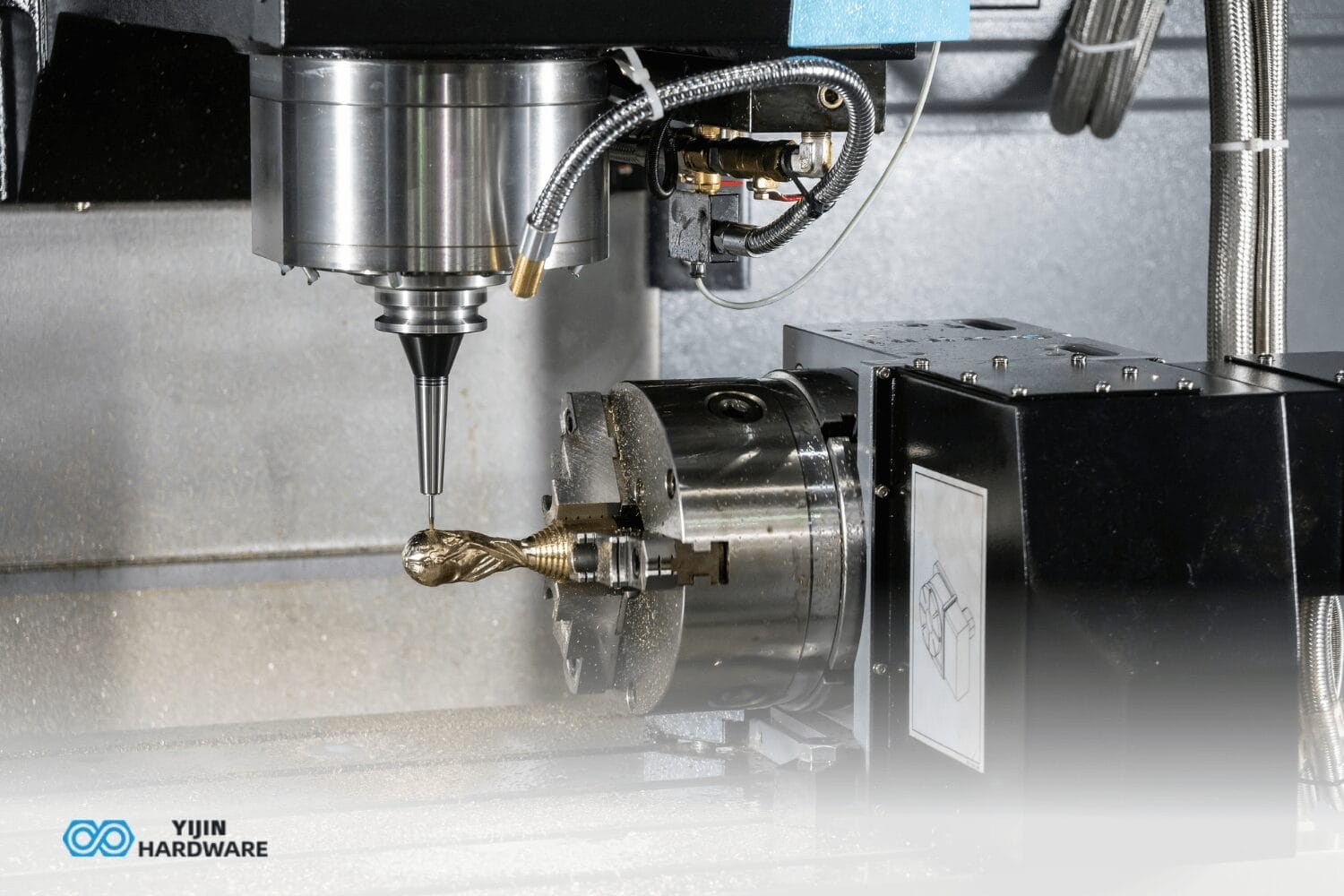
Machine Component Terminology
Absolute Programming is a coding method where all coordinates are defined relative to a fixed origin point. This method simplifies programming by eliminating the need to calculate distances from any point other than the origin.
Automatic Tool Changer (ATC) is a system that automatically changes the tools in a CNC machining center to fit whatever task is needed to process a product, without requiring human operator intervention. Modern ATCs can accommodate 20-200+ tools and complete tool changes in 2–10 seconds, significantly reducing non-cutting time.
Backlash is the slack or lost motion that occurs when direction is reversed in a machine component. It is crucial to minimize backlash to maintain precision in machining operations, particularly in high-precision environments.
Coolant in CNC machining is a liquid that reduces the heat generated during machining operations, extending tool life and improving surface finish. Common coolants include water-based emulsions, synthetic coolants, and neat oils.
Fixture is a device used to securely hold the workpiece in place during machining. Proper fixture setup is essential for achieving precise machining operations and preventing workpiece movement during the cutting process.
Spindle is the rotating axis of a CNC machine that drives the cutting tool or workpiece. The spindle is useful for maintaining precision and speed, and includes components like bearings, drive motor, and tool-holding system. Modern CNC spindles achieve runout accuracy of less than 0.0001 inches and can maintain speed constancy within 1% of the set value even under varying cutting loads.
Workpiece is an item that is being machined. It is the starting material from which the final product will be created through machining. Workpiece materials range from aluminum alloys to titanium alloys to hardened steels.
Programming Terms
CAD (Computer-Aided Design) refers to software programs that allow users to digitally design parts that are to be milled, 3D printed, or rendered. CAD models serve as the foundation for CNC machining, defining the geometry that will be created.
CAM (Computer-Aided Manufacturing) is software used to control machine tools during the manufacturing of workpieces. CAM systems generate toolpaths from CAD models and machining parameters, optimizing material removal rates while respecting tool and machine limitations. Advanced CAM software can reduce machining time by 25-50% compared to conventional programming through optimized cutting strategies.
Closed Loop System is a control system that uses feedback from sensors to continuously monitor and adjust machine operations. This system ensures accuracy by comparing the actual position with the programmed position and making real-time corrections.
G-code is the fundamental language used to control CNC machines. It consists of commands that dictate the machine’s movements and operations. While there is an ISO standard for G-code (RS-274), many machine manufacturers use proprietary extensions for advanced features. A typical CNC program may contain hundreds to thousands of G-code blocks, each representing a discrete machine action.
Home Position (Machine Zero) is the machine-designated zero point determined by physical limit switches. It does not identify the actual work origin when processing a workpiece. Home position serves as a reference point for all machine movements and is established through a homing procedure at startup, with position repeatability of ±0.0001 inches or better.
Incremental Programming is a coding method where each move is for the position of the tool at the end of the previous move, rather than from a fixed origin. This is coded with G91 and is useful for repetitive tasks or patterns within a program.
M-code is used in G-code programming to control miscellaneous functions of the CNC machine, such as coolant flow, spindle start/stop, and tool changes. Each M-code serves a specific operation, essential for automating the machining process. While G-codes control motion, M-codes handle auxiliary functions like program flow control and machine feature activation.
Tooling Terms
Ball End Mill is a cutting tool with a rounded cutting arc tip, where the arc diameter is equal to the cutting diameter. This tool is used for cutting flutes, 3D toolpaths, pocket trays, cutting board juice grooves, and much more. The hemispherical end allows for smooth blending between surfaces and for machining contoured surfaces with step-overs set at 5-10% of tool diameter for finishing operations.
Boring is a machining process that enlarges an already existing hole. It is performed using a single-point cutting tool called a bore, which allows for precise control of the hole size and finish. Boring can achieve hole diameter tolerances of ±0.0005 inches and surface finish as fine as 16 microinches Ra.
Chip Load is the amount of material removed by each tooth of a cutting tool per revolution. Managing chip load is critical for maintaining tool health, achieving good surface finish, and ensuring efficient material removal rates. Typical chip loads range from 0.001-0.020 inches per tooth, depending on tool size, material, and operation type.
End Mill is a type of cutting tool used in industrial milling applications. It is distinguished from the drill bit in its application, geometry, and manufacture. End mills are used in milling applications such as profile milling, tracer milling, face milling, and plunging.
Reamer is a type of cutting tool used to enlarge and finish an existing hole to achieve a specific size and smooth surface. Reaming follows drilling or boring and can improve hole size accuracy to within ±0.0005 inches and surface finish to 16-32 microinches Ra. Reamers turn at 1/2 to 1/3 the speed of a drill bit of the same diameter.
Tap is a tool used to cut internal threads in a hole, allowing screws or bolts to secure components. Taps are available in various thread forms and styles for different applications. CNC machines can perform tapping operations using synchronous or rigid tapping cycles that precisely coordinate spindle rotation with axial feed rate.
Toolholder is a device used to securely hold cutting tools in a CNC machine, ensuring alignment and stability during operations. Common toolholder types include collet chucks, hydraulic chucks, thermal shrink fit, and Weldon flats. Tool runout in premium holders is less than 0.0001 inches.
Process Terminology
Climb Milling is a CNC milling technique where the cutting tool moves in the same direction as the workpiece feed, reducing heat generation and improving surface finish. In climb milling, the chip thickness starts at maximum and decreases to zero, resulting in less work hardening of the material and typically 15-20% longer tool life compared to conventional milling.
Conventional Milling is a milling approach where the cutting tool moves against the direction of the workpiece feed, providing better control but potentially increasing heat and tool wear. In conventional milling, the chip thickness starts at zero and increases to maximum, which can cause rubbing at the initial contact point. This method may be preferred for machines with backlash issues or when machining materials with hard surface scale.
Depth of Cut indicates how much material is being removed from a workpiece with each pass of the tool. It is a critical parameter that affects cutting forces, tool wear, and machining efficiency. Depth of the cut is classified as roughing (0.1-0.5× tool diameter) or finishing (0.01-0.1× tool diameter).
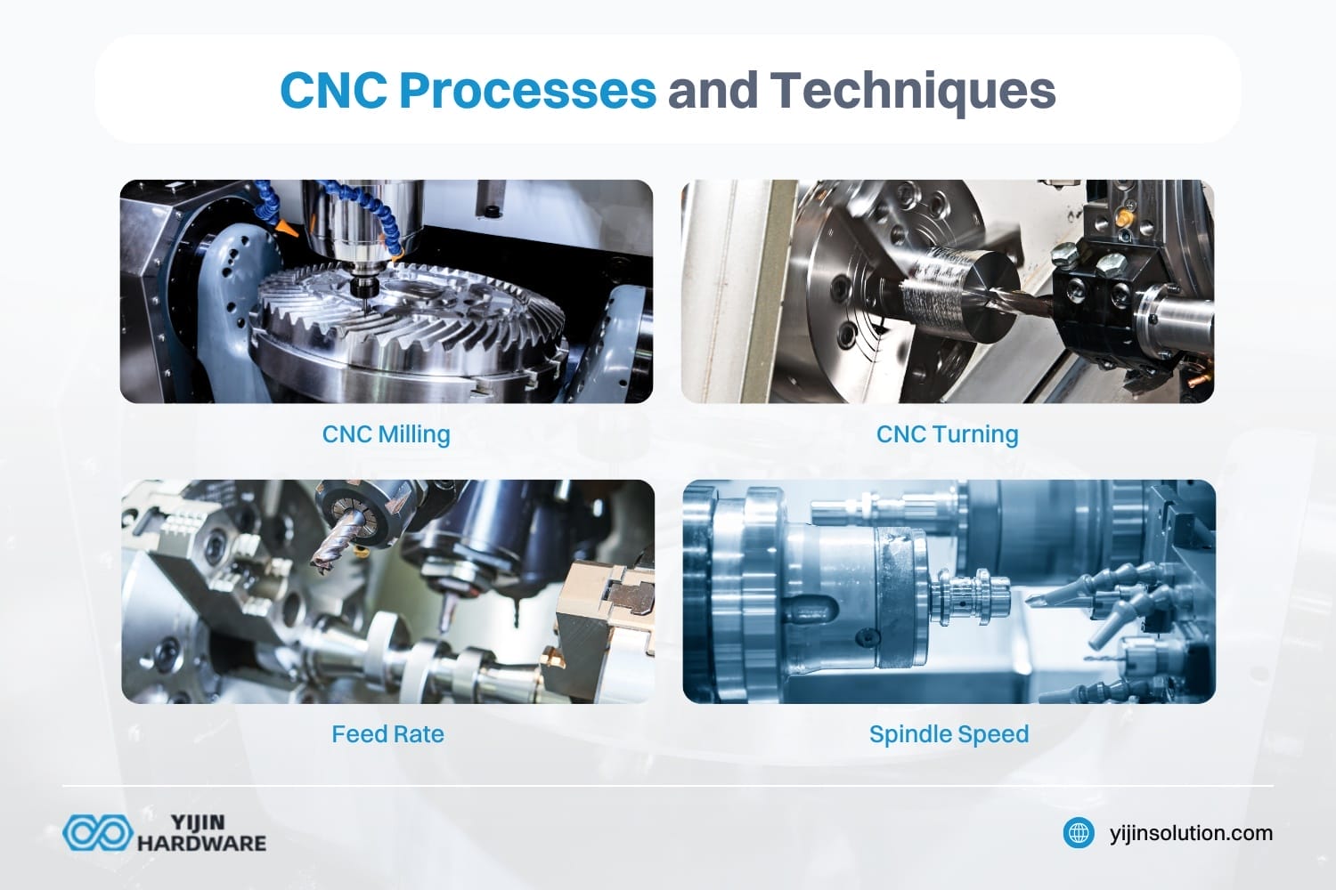
Feed Rate refers to the speed at which the cutting tool moves along a workpiece in the X and Y axis. It is usually measured in inches per minute (IPM) or millimeters per minute (mm/min). Feed rates directly impact machining time, surface finish quality, and tool life, with typical rates ranging from 5-10 IPM for hard materials to 500+ IPM for aluminum in high-speed machines.
Spindle Speed is the rotational speed of the spindle holding the cutting tool, measured in revolutions per minute (RPM). It influences chip formation, heat generation, and tool wear. Modern CNC machines offer spindle speeds ranging from 6,000 RPM in basic machining centers to 30,000+ RPM in high-speed machining centers.
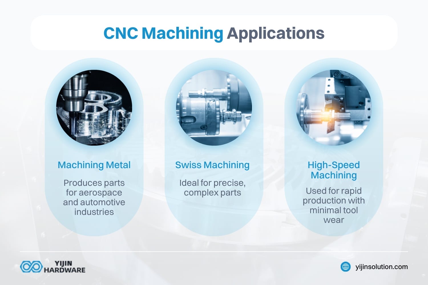
High-Speed Machining (HSM) is a machining technique characterized by high spindle speed and feed rate to achieve high material removal rates. It’s often used for cutting hard materials and when high accuracy and precision are required. HSM generally operates at cutting speeds 5–10 times higher than conventional machining, using specialized CAM strategies to maintain constant tool engagement and minimize shock loading.
Plunge Rate is the vertical speed at which the tool enters the material, measured in inches or millimeters per minute. It is set lower than the feed rate (about 40-60% of the feed rate) to reduce the shock on tool entry and prevent premature tool failure.
Roughing is the machining operation that removes large amounts of material quickly, preparing the workpiece for finer finishing passes. Roughing strategies prioritize material removal rate over surface finish, leaving 0.01-0.02 inches of material for subsequent finishing operations. Modern roughing techniques like high-efficiency milling (HEM) maintain consistent tool load to maximize material removal rates.
Finishing is the final machining operation that achieves the desired surface finish and tight tolerances on a workpiece. Finishing passes remove small amounts of material (0.005-0.015 inches) using higher speeds, lower feeds, and specialized toolpaths to achieve surface finishes as fine as 16-32 microinches Ra.
What Terms Include Factors that Affect CNC Machining Precision?
CNC machining precision is influenced by numerous factors related to the machine, tooling, workpiece, and environment. We’ve outlined the common terms that you’ll often encounter when discussing CNC machining here.
Machine Factors
Machine Rigidity determines how well the machine resists deflection undercutting forces. Higher rigidity reduces vibration and improves machining accuracy. Premium machines use cast iron or polymer concrete bases, rigid box ways, and optimized structural designs to minimize deflection under load.
Axis Resolution defines the smallest increment of movement a machine can execute. Modern CNC machines typically offer resolution of 0.0001 inches (0.001 mm) or better, with high-precision machines achieving 0.00001 inches (0.0001 mm) resolution through high-resolution encoders and precision drive systems.
Thermal Stability affects how machine dimensions change with temperature variations. Temperature fluctuations can cause thermal expansion of machine components, affecting precision.
Control System Capability influences how accurately the machine can follow programmed paths. Modern CNC controls offer features like look-ahead (processing hundreds of blocks in advance), nanometer-level interpolation, and advanced acceleration/deceleration control to maintain accuracy even during high-speed operation.
Tooling Factors
Tool Deflection occurs when cutting forces bend the tool slightly during machining. This deflection can cause dimensional errors, especially with long, thin tools or deep cuts. When machining with a length-to-diameter ratio greater than 4:1, tool deflection becomes a significant concern, potentially causing dimensional errors of 0.001-0.010 inches if not compensated for.
Tool Wear changes the tool’s dimensions and cutting characteristics over time. Progressive wear can lead to dimensional variation in machined parts and degraded surface finish. Tool life can vary dramatically based on material (from 10 minutes in titanium to 10+ hours in aluminum) and must be monitored to maintain precision.
Tool Holding System affects how securely and accurately the tool is held in the spindle. Precision toolholders with runout of less than 0.0001 inches are best for high-precision machining. Hydraulic and shrink-fit holders offer the best runout control and rigidity for precision applications.
Workpiece Factors
Material Properties influence machinability, cutting forces, and thermal behavior during machining. Different materials require specific cutting parameters and strategies to achieve optimal results. Materials with low thermal conductivity (like titanium) or high hardness (like hardened steel) present special challenges for maintaining precision.
Workpiece Rigidity determines how well the part resists deformation during machining. Thin-walled parts or those with delicate features may deflect undercutting forces or clamping pressure. For thin-walled components (wall thickness/height < 0.1), specialized machining strategies like maintaining constant engagement and reduced cutting forces are essential.
Workholding Method affects part stability and reference accuracy during machining. Inadequate workholding can allow the part to shift or vibrate, compromising precision. Workholding systems must balance clamping force (to prevent movement) with minimizing distortion, particularly for thin-walled or precision components.
Environmental Factors
Temperature Fluctuations cause thermal expansion and contraction of both the machine and workpiece. For precision machining, temperature-controlled environments (±1 °C) are often necessary, with high-precision work requiring even tighter control (±0.1 °C).
Vibration from external sources or from the cutting process itself can compromise surface finish and dimensional accuracy. Precision machines are often installed on isolation foundations and incorporate vibration damping features in their construction.
Humidity can affect both materials and machine performance in extreme cases. Control of relative humidity (around 40-60%) helps maintain material dimensional stability and prevents corrosion issues that could affect precision.
What are the Different Types of CNC Machines? | Terminology
CNC machines vary widely based on their capabilities, configurations, and applications. Understanding the different types and terms helps in selecting the right machine for specific manufacturing requirements.
Vertical Machining Center (VMC) is a CNC machine with a vertically oriented spindle that approaches the workpiece from above. VMCs are versatile machines suitable for a wide range of parts and are generally more economical than their horizontal counterparts.
Horizontal Machining Center (HMC) is a milling machine with a horizontally oriented spindle. This configuration offers better chip evacuation, support for heavier cutting, and often includes pallet changers for higher productivity.
CNC Lathe is a machine that rotates the workpiece on its axis to perform operations like cutting, sanding, knurling, drilling, or deformation using stationary tools. Modern CNC lathes can include live tooling for milling operations.
Swiss-Type Lathe is a specialized CNC lathe designed for high-precision, small-diameter parts. It features a guide bushing that supports the material close to the cutting tool, reducing deflection and enabling exceptional accuracy on long, slender parts.
What are CNC Axes and How do they Control Machine Movement? | Terminology
CNC machines operate on multiple axes, which define the planes of motion and determine the machine’s capabilities for creating complex geometries. Here are what specific axis terms mean and how they’re applied.
Primary Linear Axes
X-Axis represents horizontal movement from left to right (or right to left) relative to the operator. On a lathe, the X-axis controls the tool’s distance from the centerline of the rotating workpiece.
Y-Axis represents horizontal movement from front to back (or back to front) relative to the operator. This axis is present in milling machines, but not in standard lathes.
Z-Axis represents vertical movement up and down. In milling machines, this controls the height of the cutting tool above the workpiece, while in lathes it controls movement along the length of the workpiece.
Rotational Axes
A-Axis rotates around the X-axis, allowing tilting movements in the Y-Z plane. This is essential for 5-axis machining of complex contoured surfaces.
B-Axis rotates around the Y-axis, enabling tilting in the X-Z plane. B-axis capability is particularly valuable for machining parts with features at multiple angles.
C-Axis rotates around the Z-axis, providing rotational movement in the X-Y plane. On a mill-turn center, the C-axis often controls the rotation of the spindle for precise angular positioning.
Multi-Axis Configurations
3-Axis Machines control movement along the X, Y, and Z linear axes, suitable for machining parts with features that can be accessed from a single direction.
4-Axis Machines add one rotational axis (typically A or C) to the three linear axes, allowing machining on multiple sides of a part without manual repositioning.
5-Axis Machines incorporate two rotational axes in addition to the three linear axes, enabling complex geometries with undercuts and features at various angles to be machined in a single setup.
Mill-Turn Centers combine milling and turning capabilities with multi-axis control, allowing complete machining of complex parts in a single setup, reducing handling and improving accuracy.
What are Terms for Main CNC Machining Processes?
CNC machining encompasses several distinct processes, each suited to particular manufacturing requirements and component geometries. We’ll cover two popular types of CNC processes and their definitions here.
How does CNC Milling Work?
CNC Milling is a machining process that uses rotating cutting tools to remove material from a workpiece. In milling, the cutting tool rotates at high speed (1,000-30,000 RPM) while the workpiece remains stationary, and either the tool or workpiece moves along multiple axes to create the desired shape.
What is CNC Turning and How does it Differ from Milling?
CNC Turning is a machining process where the workpiece rotates while a single-point cutting tool moves linearly to remove material. It is primarily used to create cylindrical parts with features like diameters, tapers, threads, and grooves.
FAQs on CNC Machining Terminology | Essential CNC Vocabulary
How can there be more than 3 axes?
A CNC machine can have more than three axes by incorporating rotational and linear movements. The machine tool can move in multiple directions, enhancing flexibility and precision.
What is electrochemical milling?
Electrochemical milling is a CNC machining process that removes material using chemical reactions instead of cutting. A device used to control electrical currents dissolves metal, shaping the workpiece precisely.
What does CNC DNC stand for?
CNC DNC stands for Direct Numerical Control, a system used to control multiple machines simultaneously. The CNC controller sends real-time instructions to connected machines, optimizing workflow efficiency.
Back to Top: CNC Machining Terminology | Essential CNC Vocabulary