
The choice between CNC Machining (Subtractive) and 3D Printing (Additive) hinges on a specific tri-factor of requirements: geometric complexity, production volume, and mechanical load capacity.
While CNC machining shears material from a solid block to guarantee precision and isotropy, 3D printing fuses material layers to offer geometric freedom and zero tooling costs.
Industrial Safety Disclaimer
Manufacturing involves significant hazards. CNC machining presents risks from high-speed rotation and sharp debris. Metal 3D printing (DMLS/SLM) involves handling reactive metal powders that pose explosion and inhalation risks. Always adhere to ISO/OSHA safety standards and use appropriate PPE.
Key Takeaways: The Fast Decision Shortlist
For immediate decision-making, this shortlist categorizes the “Best Choice” based on critical engineering constraints like tolerance, strength, and internal geometry.
| Требование | Best Choice | Why | Watch-outs |
|---|---|---|---|
| Жесткие допуски | Обработка с ЧПУ | Reliable ±0.01mm accuracy. | High setup cost for singles. |
| Internal Channels | 3D-печать | Layers allow buried features. | Inspection requires a CT scan. |
| Высокая прочность | Обработка с ЧПУ | Preserves isotropic billet properties. | Tool reach limitations. |
| Lowest Cost (1–10) | 3D-печать | Zero tooling/setup cost. | High material cost (powder). |
| Lowest Cost (500+) | Обработка с ЧПУ | Fast cycle times amortize setup. | Material waste (chips). |
| Отделка поверхности | Обработка с ЧПУ | Smooth as-machined (Ra 0.8–3.2). | 3D printing has layer lines. |
CNC Machining vs 3D Printing (What the Difference Means for Your Part)
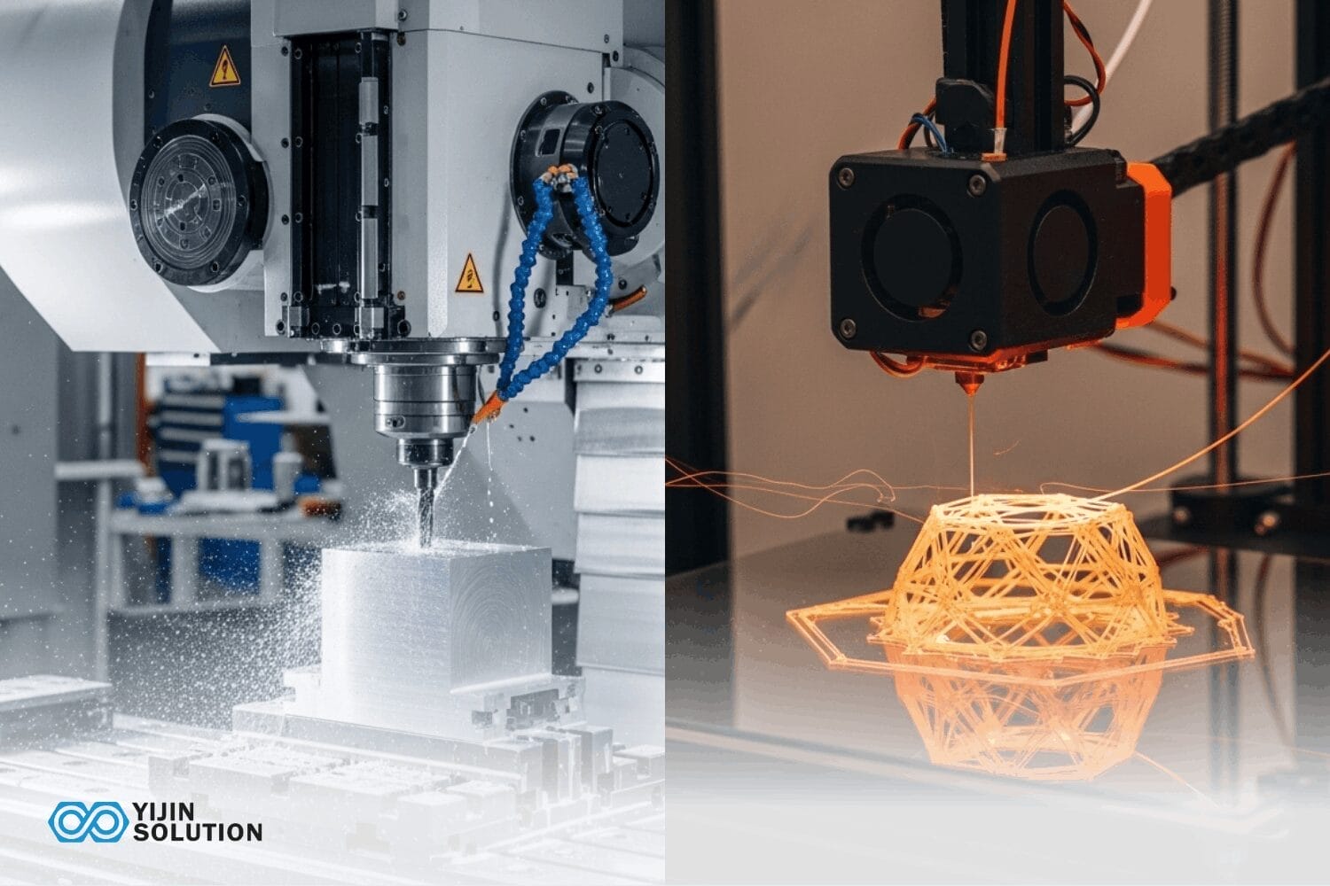
The fundamental difference lies in the physics of creation: CNC machining removes material from a solid block to reveal the part, while 3D printing builds the part layer-by-layer from feedstock.
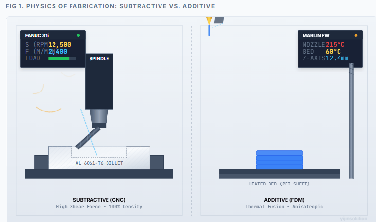
Figure 1 Analysis: This schematic illustrates the fundamental divergence in fabrication physics.
Left (Subtractive): A high-torque spindle drives a cutting tool at 12,000 RPM to mechanically shear material from a solid, cold-rolled billet clamped in a vice.
The “load” indicator reflects cutting resistance. Because the part is carved from a certified block, it retains 100% parent material density and a uniform (isotropic) grain structure.
Right (Additive): A thermal print head heats thermoplastic to its glass transition point (215°C) and deposits it onto a build plate.
The process relies on thermal fusion between layers. Note the “layer lines” in the cross-section; these interfaces act as potential stress concentrators, resulting in Anisotropic mechanical properties (typically 40-50% weaker in the vertical Z-axis).
CNC machining (Subtractive) — Predictable Integrity
CNC machining is a subtractive process where rotating tools shear material away from a certified billet, preserving the structural integrity of the original stock.
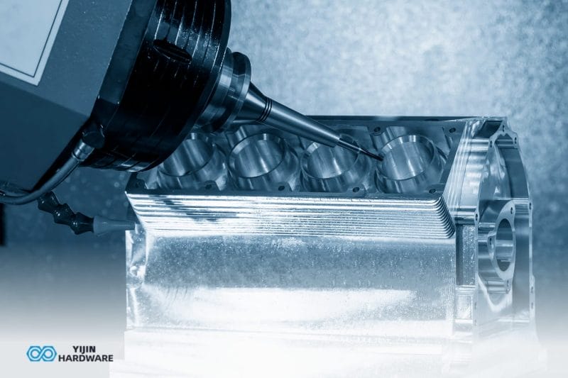
5-Axis Machining reduces setups and allows access to complex features while maintaining high rigidity.
As detailed by Groover in Fundamentals of Modern Manufacturing, subtractive processes remove material from solid stock, maintaining 100% material density, ensuring predictable mechanical performance.
For deeper technical data on alloy machinability and tolerance stacks, consult our CNC machining resources.
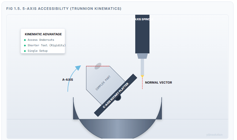
Fig 1.5 Kinematics: By tilting the workpiece (A-Axis) and rotating it (C-Axis), 5-axis machining aligns complex features (like the angled bore shown above) directly with the rigid Z-axis spindle. This eliminates the need for manual refixturing and allows for shorter, stiffer cutting tools compared to reaching with a long tool on a 3-axis machine.
3D printing (Additive) — Geometry Freedom vs. Process Reality
3D printing is an additive process that fuses material layers to create geometry, offering design freedom at the cost of structural anisotropy and surface roughness.
Fused Deposition Modelling (FDM) parts often exhibit 55-60% Z-axis strength compared to X/Y axes due to layer adhesion limits.
Ahn et al. highlight how layer-by-layer fusion introduces micro-voids and bond lines, creating directional weakness known as Anisotropy.
To navigate these specific layer constraints and orientation rules, refer to our 3D printing resources.
| Технология | Типовое применение | Core Constraint |
|---|---|---|
| CNC 3-Axis | Prismatic parts, simple brackets. | Tool access. |
| CNC 5-Axis | Impellers, complex housings. | Cost. |
| FDM | Visual models, jigs. | Weak Z-axis. |
| SLS | Functional nylon, good nesting. | Surface roughness. |
| DMLS/SLM | Metal assemblies. | High cost / high density. |
Cost Comparison (Where the Money Actually Goes)
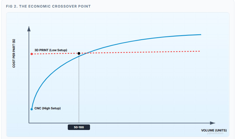
The cost dynamics of CNC vs. 3D printing are defined by the inverse relationship between “Setup Costs” (NRE) and “Variable Costs” (Unit Price). Amortisation refers to spreading the one-time setup cost over the total quantity of parts produced.
CNC cost drivers
CNC cost drivers are heavily front-loaded, dominated by programming time (CAM), fixture creation, and machine setup, which can make single parts prohibitively expensive.
Material waste is significant; subtractive processes can waste 40-60% of expensive alloys like Titanium. Tool wear also contributes 10-15% to the run rate on hard metals.
3D printing cost drivers
3D printing cost drivers are centred on the high price of feedstock materials (powder/filament) and slow machine cycle times, which remain constant regardless of volume.
Metal powder can cost 10-20x more per kilogram than standard billet. Machine time amortisation contributes significantly (20-30%) because print runs take hours, not minutes.
Unit cost vs volume (The Crossover)
The “Cost Crossover” point typically occurs between 50 and 100 units, where the efficiency of CNC machining overtakes the low-setup advantage of 3D printing. For simple parts, CNC wins early; for complex lattices, 3D printing may remain cheaper up to 300 units.
Amortizing setup costs over high volume drastically lowers per-unit price in CNC , making it the economic winner for production runs.
| Объем | Winner | Logic |
|---|---|---|
| 1–5 Parts | 3D-печать | Zero tooling. Instant start. |
| 5–50 Parts | Toss-up | Simple = CNC; Complex = Print. |
| 50–500 Parts | Обработка с ЧПУ | Setup amortizes; speed wins. |
| 500+ Parts | Обработка с ЧПУ | Scale economics (up to 60% cheaper). |
Precision & Tolerances (What You Can Reliably Hold)
Precision capabilities distinguish the two processes, with CNC machining consistently holding tighter tolerances and superior surface finishes compared to additive methods.
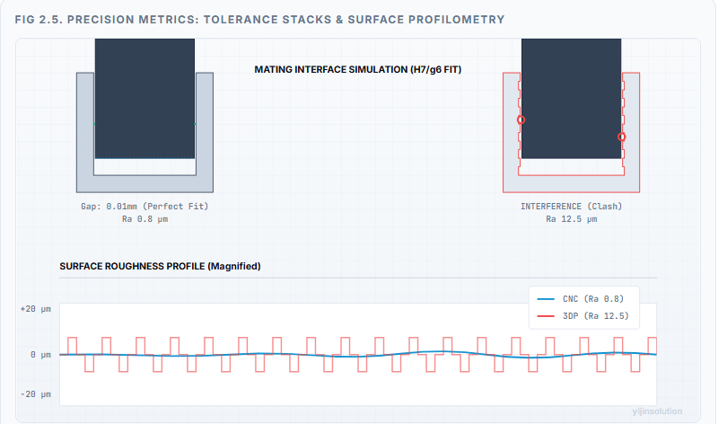
Figure 2.5 Analysis: Precision in manufacturing isn’t just about the nominal dimension; it’s about surface deviations. The graph above contrasts the Roughness Profile (Ra). CNC machining (Blue) produces a nearly flat profile, ensuring a “Running Fit” (H7/g6) where a shaft spins freely in a bore. 3D Printing (Red) creates a “stair-step” profile; even if the nominal diameter is correct, the peaks of the layers will cause interference, requiring extensive post-processing (sanding/reaming) to assemble.
CNC machining precision (The Winner)
CNC machining is the undisputed winner for precision, capable of holding standard tolerances of ±0.025mm and high-precision tolerances of ±0.0025mm for defense applications.
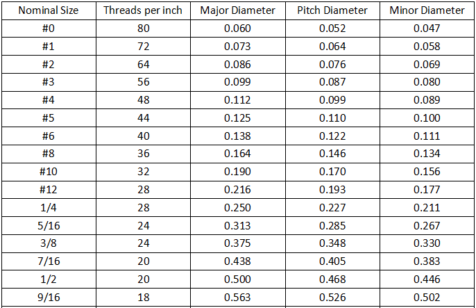
This precision is essential for mating surfaces, bearing seats, and Class 2B/3B threads. Subtractive methods create naturally smooth surfaces (Ra 1.6-3.2) without post-processing.
3D printing precision (The Variable)
3D printing precision varies by technology, with FDM typically holding ±0.5mm and high-end DMLS achieving ±0.1mm, often requiring post-machining for critical features.
Thermal shrinkage and layer stepping limit the achievable tolerance. Thermal gradients during sintering cause part warping or shrinkage necessitating CNC post-processing for tight fits.
| Требование | Best Choice | Примечания |
|---|---|---|
| Tolerance < ±0.05mm | ЧПУ | – |
| Threads required | CNC or 3D Print | Use Print + Inserts |
| Ra (Surface Roughness) < 1.6μm | CNC or 3D Print | Use Print + Polish |
Performance & Mechanical Properties
Mechanical performance is defined by the material’s internal structure, with CNC parts retaining the isotropic strength of the stock and 3D printed parts exhibiting anisotropic weakness.
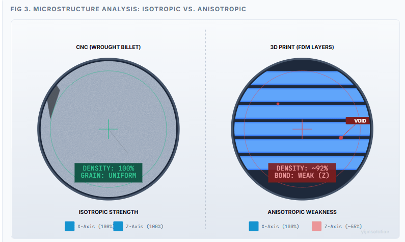
Microstructural Integrity Analysis
Left (CNC Billet): The microscopic view reveals a uniform, random grain structure characteristic of rolled or forged metals. Because the material is continuous, tensile stress propagates evenly in all directions (Isotropic). There are no internal voids, guaranteeing 100% density and predictable fatigue life.
Right (3D Printed): The structure is defined by distinct laminar bands. The interfaces between these layers rely on thermal fusion (remelting), which is rarely perfect. Notice the micro-voids (red indicators) where layers meet; these act as “crack initiation points” under load. This results in Anisotropy, where the Z-axis (vertical pull) strength is often 40-50% lower than the X/Y axes due to delamination risk.
CNC machining performance
CNC machined parts exhibit Isotropic properties, meaning their tensile and yield strength are uniform in all directions (X, Y, Z) because they are cut from rolled or forged billet. This makes CNC the default for high-load, fatigue-critical components.
The uniform grain structure of billet (Entity) resists cyclic loading evenly (Action), preventing premature structural failure (Result).
3D printing performance
3D printed parts are inherently Anisotropic, often exhibiting significantly lower strength in the Z-axis (vertical) due to the nature of layer-by-layer bonding. While DMLS metal parts can reach 99%+ density, they often require HIP (Hot Isostatic Pressing) to relieve stress and close micro-voids.
FDM parts may only retain ~55% of their strength in the Z-axis compared to the X-axis.
| Condition | Selection |
|---|---|
| High Cyclic Load | CNC (Safer) |
| High Heat/Pressure | CNC (Wrought is better) |
| Оптимизация веса | 3D Printing (Lattices) |
Materials & Application Fit
Material selection is often a deciding factor, as CNC machining supports virtually any solid material, while 3D printing is limited to specific thermoplastics and sintered powders.
Material options in CNC machining
CNC machining offers the full spectrum of commercial stock, including high-performance aerospace alloys like 7075 Aluminum, Ti-6Al-4V, and engineering plastics like PEEK.
You are using the exact material certified for the end application. CNC is the only way to process specific hardened steels (e.g., M50) in their final state.
Material options in 3D printing
3D printing material options include various polymers (Nylon PA12, ABS) and specific metal powders (AlSi10Mg, Maraging Steel) tailored for sintering.
Printed metals (e.g., AlSi10Mg) are alloys designed for printing, not identical to wrought 6061 Aluminum.
Proprietary powder formulations enable the sintering process but may differ chemically from standard industrial bar stock.
Quick Check:
- Need 7075 Aluminum? → CNC(Hard to print).
- Need Maraging Steel? → DMLS(Good candidate).
Geometry & Design Constraints
Geometry and design constraints dictate the process, as CNC is limited by tool access (undercuts) while 3D printing thrives on complexity (lattices, internal channels).
Geometry strengths of CNC
CNC machining excels at creating precision flats, bores, and tapped holes, but is limited by the “Line of Sight” requirement for the cutting tool. Internal undercuts or hollows require multi-axis setups or are physically impossible.
Best for solid, prismatic parts with accessible features. Conversely, for thin-walled enclosures where material removal is inefficient, our Направляющие из листового металла offer a distinct fabrication pathway.
Geometry strengths of 3D printing
3D printing eliminates tool access limitations, enabling features like Conformal Cooling channels and internal lattice structures that are impossible to machine.
This allows for Assembly Consolidation, printing one complex part instead of assembling ten simple ones. Layer-wise construction builds internal features without tooling access, enabling previously impossible geometries.
Lead Time & Iteration Speed
When 3D printing is fastest
3D printing is fastest for “Day One” prototypes, often delivering a physical part within 24-48 hours by bypassing the need for CAM programming and fixture creation. Ideal for fit-checks and visual models. Speed advantage diminishes as quantity increases.
When CNC is faster overall
CNC becomes faster overall once production begins (500+ parts), as high-speed machining cycles take seconds compared to the hours required for printing layers. Once the setup is complete, material removal is rapid.
Quality Control & Inspection
CNC Inspection
Established ISO standards; easy CMM access. Surface probing verifies dimensions quickly.
3DP Inspection
Internal voids and powder entrapment are risks. Often requires expensive CT scanning to detect internal
How to Choose CNC Machining vs 3D Printing (Decision Framework)
Choosing between CNC machining and 3D printing requires a decision framework that balances tolerance needs against volume and geometric complexity.
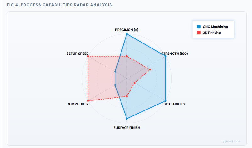
Figure 4 Analysis: This radar chart visualizes the “Shape of Performance” for each technology. CNC (Blue) dominates the right hemisphere (Precision, Strength, Scalability), making it the engine of production. 3D Printing (Red) dominates the left hemisphere (Speed, Complexity), defining it as the engine of innovation and prototyping.
Choose CNC if…
Tolerances < ±0.025mm, Qty > 100, Isotropic strength needed.
Choose 3DP if…
Geometry “impossible” to cut, Qty < 10, Lead time < 72 hours.
Choose Hybrid if…
Print complex near-net shape → CNC machine critical mating surfaces.
| Criterion | Обработка с ЧПУ | 3D-печать |
|---|---|---|
| Стоимость | High Setup / Low Unit | Low Setup / High Unit |
| Точность | High (±0.01mm) | Low-Mid (±0.1mm) |
| Speed (1 part) | Slow (Setup) | Fast (Print) |
| Speed (100 parts) | Fast (Cycle) | Slow (Layering) |
| Прочность | Isotropic (Uniform) | Anisotropic (Z-weak) |
| Finish | Smooth | Layer Lines |
Quote-Ready Checklist:
- Digital Files (STEP/STL + PDF).
- Material (Stock vs. Powder).
- Quantity (1 vs 1000).
- Critical Tolerances (Circle on PDF).
- Finish (As-Machined vs Polished).
- Certifications (ISO/AS9100).
Yijin Solution Support
Yijin Solution provides a unified manufacturing solution, leveraging a 5,000+ sqm facility to deliver both прецизионная обработка с ЧПУ и advanced 3D printing services. We process 8M parts/month with AS9100, ISO 9001, and ITAR certifications. Our capability includes standard ±0.05mm and high-precision ±0.01mm machining.
CNC Machining vs. 3D Printing FAQs
Is CNC machining more accurate than 3D printing?
Yes, typically 10x more accurate (±0.0025mm vs ±0.05mm).
Is 3D printing cheaper than machining?
Only for low volumes (1-10 parts) or complex geometries.
When should I use metal 3D printing (DMLS) instead of CNC?
For complex internal channels, lattices, or weight reduction.
Can I prototype with 3D printing and manufacture with CNC later?
Yes, but design adjustments (DFM) will likely be needed.
Вернуться к началу: CNC Machining vs. 3D Printing: Cost, Precision & Performance