What Is Tool Offset?
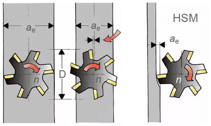
Tool offset: The compensating displacement of the tool position along the direction parallel to the control coordinate.
Tool offset is the relative displacement applied to the coordinate axes of a machine tool during all or a specified part of a machining program. The displacement direction of the axis is determined by the positive or negative bias value.
The concept of compensation (offset) is used a lot in our life. For example, when a driver drives his car around a rock, he should make the turn go around the side of the rock, and also take into account that the car has a certain width.

So the centerline of the car is at least half a car width away from the rock. In the 60s ~ 70s the 20th century, there was no concept of compensation in CNC machining, so programmers had to route around the tool theory and the actual route of relative relation to programming.
It is easy to produce an error, through the cutting tool offset/compensation, which not only can simplify the programming but can also be in the same process of parts in the roughing and semi-finishing and finish machining, improving production efficiency, reducing the labor intensity of technical personnel.
Tool Offset Process
The tool offset of the CNC control system is the process of calculating the tool center trajectory carried out by the CNC system.
Programming is carried out directly according to the outline shape of the parts without considering the tool diameter, and the actual tool radius is stored in a programmable tool radius offset register.
In the process of machining, the CNC system automatically calculates the tool center track according to the part program and the tool diameter in the tool offset register and completes the machining of the parts.
Modern CNC systems generally have 16, 32, 64, or more programmable tool offset registers, which are numbered for tool compensation.
During CNC programming, only the register number corresponding to the tool compensation parameter can be processed.
When the tool compensation is executed, the intersection calculation method is adopted, that is, two paragraphs are read before the start of each paragraph, the intersection point is calculated.
The tool compensation vector path is added to the left or right of each forward direction according to the vector at the start stage, thereby processing a workpiece that conforms to the contour of the pattern.
Discussion on Tool Offset
Tool Length Compensation
Tool length is a very important concept, when we program a machining part, we must first specify the programming center of the part, and then establish the workpiece programming coordinate system.
And this coordinate system is only a workpiece coordinate system, zero point is generally on the workpiece. Since the length of each tool is different, the length compensation is only related to the Z coordinate.
For example, we want to drill a hole of 50 m depth and tap a hole of 45 m depth with a drill of 250 m length and a tap of 350 m length.
First, use a drill to drill a hole with a depth of 50 mm. At this time, the machine tool has set the workpiece at zero point. When tapping is replaced, if both tools start processing from the set zero point, the tap is longer than the drill and the tap is too long which may damage tools and workpieces.
At this time, if the tool compensation is set, the length of the tap and the drill are compensated. Therein, after the zero setting of the machine tool, even if the tap and the drill are different in length.
Due to the existence of compensation when the tap is called, the zero Z coordinate has automatically compensated the length of the tap to Z+ (or Z), to ensure the correct processing zero.
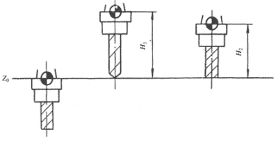
Tool length offset is carried out by instructions G43, G44, and G49, which can compensate for the change of tool length at any time without changing the program.
The compensation amount is stored in the memory of instructions by H code. G43 represents the addition of the compensation amount in the memory and the terminal coordinate value of the program instruction
G44 represents the subtraction, and the tool length bias can be canceled by G49 instruction or H 00 instruction.
If the program segment N80 G43 Z56 H 05, 05 memory value is 16, it means that the terminal coordinate value is 72 mm.
The value of the compensation amount in the memory can be pre-stored in the memory by M DI or DPL, or the program segment instruction G10 P05 R16.0 can be used to indicate that the compensation amount in the 05 memory is 16 M M.
There are two ways of tool length compensation:
(1) Use the actual length of the tool as the tool length compensation. Using tool length as compensation is to measure the tool length with a tool counter, and then input this value into the tool length compensation register as tool length compensation.
First, the use of tool length as tool length compensation can avoid the constant modification of tool length offset in different workpiece processing.
In this case, can be by certain tool numbering rules, to do files for each tool, with a small sign to write the relevant parameters of each tool, including the length of the tool, radius, and other information.
Secondly, the use of tool length as tool length compensation can let the machine tool side processing operation, while on the tool instrument for other tool length measurements.
And do not have to take up the machine tool running time because of the tool on the machine tool, so you can give full play to the efficiency of the machining center.
(2) Use the distance value (positive or negative) between the tooltip in the Z direction and the programmed zero point as the compensation value.
This method is suitable for only one person to operate the machine tool and there is not enough time to use the tool instrument to measure the length of the tool so when processing another workpiece with a tool.
It is necessary to re-set the tool length compensation. When using this method for tool length compensation, the compensation value is the tooltip movement distance when the spindle moves from Z coordinate zero of the machine tool to program zero of the workpiece, so the compensation value is always negative and very large.
Tool Radius Compensation
Tool radius compensation just as the use of tool length compensation in programming does not consider the length of the tool, because of the tool radius compensation, we can not consider the diameter of the tool too much in programming.
Tool length compensation applies to all tools, and tool radius compensation is generally only used for milling tools. Tool radius compensation is used when the milling cutter processes the internal and external contour of the workpiece.
Because tool radius compensation is a difficult instruction to understand and use, many people do not want to use it in programming.
But once we understand and master it, it will bring great convenience to our programming and processing. When the programmer is ready to make up a milling cutter to process the shape of a workpiece program.
First of all, according to the shape of the workpiece size and the radius of the tool meticulous calculation of coordinate values to determine the path of the tool center.
The shape of a workpiece is divided into rough processing and finishing, and the rough processing program is only completed after rough processing, because of the rough processing, the size of the workpiece has changed.
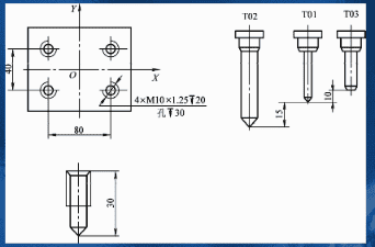
At this point, if you use tool radius compensation, these troubles are all solved. We can ignore the tool radius and program according to the workpiece size, then place the tool radius as the radius compensation in the radius compensation register.
Whether temporarily replacing the milling cutter or performing rough and finishing machining, we only need to change the tool radius compensation value to control the size of the workpiece’s external dimensions without modifying the program.
The use of tool radius compensation is performed by instructions G41, and G42. The compensation has two directions, by the left and right-hand rule: G41 has left compensation.
By the left-hand rule; G42 is right compensation, which conforms to the right-hand rule.
When using G41 and G42 for radius compensation, the following steps should be taken: set the tool radius compensation value;
Allow the tool to move so that compensation is effective (the workpiece cannot be cut at this time);
To properly cancel the radius compensation (and the workpiece cannot be cut at this time), remember to use the G40 command to cancel the compensation only after the tool has been completely cut and safely exited the workpiece.
Fixture Offset Compensation
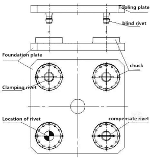
Using fixture offset compensation, like tool length and radius compensation, frees the programmer from having to consider the position of the workpiece fixture.
When machining small workpieces on a machining center, multiple workpieces can be clamped in one tooling.
When programming, programmers do not need to consider the coordinate zero point of each workpiece during programming but only need to program according to their respective programming zero points.
Then use the fixture offset function to move the programmed zero point of the machine tool on each workpiece.
Fixture offset compensation is performed by fixture offset instructions G54 ~ G59. Another method is to use the G92 instruction to set the workpiece coordinate system.
When one workpiece is finished and the next workpiece is started, the G92 instruction is used to reset the new workpiece coordinate system.
The Angle Compensation
The intersection of two planes is an included Angle, which may produce overcutting and lead to machining error. The included Angle compensation (G39) can be used to solve the problem.
When using the included Angle compensation (G39) instruction, it should be noted that this instruction is modeless and only valid in the program section of the instruction. It can only be used after G41 and G42 instructions.
CNC Tool Compensation Function
The shape and size of each cutter on the tool rest of the CNC lathe are different, and the installation position is also different.
When processing must take into account the tool installation, tip wear, and tip radius of the machining parts caused by the error, otherwise can not be processed out of the drawing requirements of the shape of the parts.
Therefore, the tool compensation function must be correctly used to improve the machining quality of parts.
Tool Offset Compensation
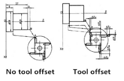
When machining parts on a CNC lathe, multiple tools are used. The installation position and geometry of each tool are different, and the length of the tool extending from the tool holder is also inconsistent.
In programming, it is assumed that the position of each tool relative to the programming origin is The same, so you need to use the tool position compensation function.
Figure 2a shows the feed track of the tipping point of the No. 1 tool as the reference tool, and there is no deviation in the position of each tool on the tool holder.
Figure 2b shows the offset of other tooltip points relative to the reference tooltip, that is, there is tool position deviation.
If the T0404 instruction is used to call the No. 4 non-reference tool to run the same program as the No. 1, the tool nose point of the No. 4 tool will move from the deviation position to the reference tool nose point position, namely, point A, and go out of the same entry as the No. 1 tool.
Given the trajectory, as shown by the solid line in Figure 2b, it indicates that the offset compensation has been successfully performed on the No. 4 non-reference tool.
Tip Arc Radius Compensation
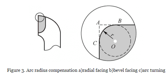
CNC lathe programming and tool setting operations are based on the ideal sharp turning tool tip point. To increase the tool life and reduce the roughness of the machined surface, the turning tooltip in actual machining is not an ideal point.
There is always an arc with a small radius, and the wear of the tooltip will also change the radius of the small arc.
The purpose of tooltip radius compensation is to solve the machining error caused by the tooltip arc. CNC programming assumes that the fixed tool points move along the contour of parts for turning, but in fact, each point on the tool point arc may be the cutting point.
When machining the end face or cylinder, the moving track of the cutting edge coincides with the contour of the parts, and no machining error will be generated. When machining arcs or conical surfaces.
The two axes of the lathe are linked, and the moving track of the cutting edge does not coincide with the contour of the parts, which will cause an undercutting or over-cutting phenomenon, as shown in Figure 3.
By using the tool radius compensation function, the tool path refers not to the tooltip, but to the movement path of the center of the arc of the blade on the tooltip.
Programmers to imaginary points according to the actual parts contour programming, numerical control system using the nose radius compensation function automatically calculates the point of the actual trajectory, the lathe tool deviates from the value of the part outline a tool radius, the blade, and the workpiece contour tangent, thereby eliminating the influence of the workpiece shape point arc radius, work out the requirements of the workpiece contour.
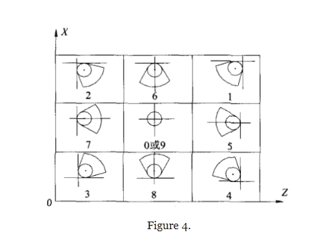
The tooltip arc radius compensation is added or canceled by the tooltip arc radius compensation number specified by code G412G422G40 and code T. shown in Figure 4.
CNC Turning Tool Type
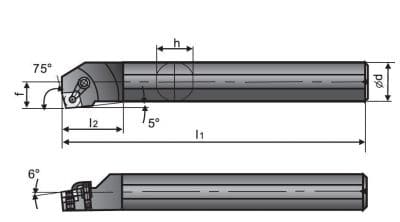
The tools used by CNC lathes can be divided into cylindrical turning tools, inner hole turning tools, thread turning tools, grooving cutters, and so on.
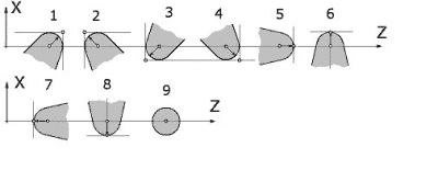
According to the classification of tooltip shape, CNC turning tools can be divided into pointed turning tools, round turning tools, and forming turning tools, as shown in Figure 5.
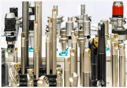
Figure 5.
Pointed Turning Tool
The cutting edge of the pointed turning tool is linear and consists of the main cutting edge and the auxiliary turning edge. For example, the commonly used outer circle turning tool, end face turning tool, grooving tool, and so on are pointed turning tools.
These tools are generally used to process parts of the inner and outer circular surface, end face, grooves, etc., the tip of the tool generally with a radius of 0.2-1.2mm arc.
Round-Nose Turning Tool
The main cutting edge of the round nose turning tool is a circular arc, and the position of the tip is not fixed during processing, which may be at any point on the round head blade.
The radius of the circular turning tool has nothing to do with the shape of the part, but the influence of the radius of the circular turning tool on the machining should be considered because the tool point is at the center of the circle.
The round nose turning tool is generally used to process the forming surface which is composed of various curves.
Forming Tool
The size and shape of the cutting edge of the forming turning tool are consistent with the outline of the parts, and its processing has certain limitations. In addition to the thread turning tool, the forming tool is seldom used in CNC turning.
Application of Tool Compensation for CNC Lathe
Change the tool complement to adapt to the change of the tool in the automatic machining process of parts, the application of the tool complement can avoid the work of remodifying the program when the tool wear, regrinding, or replacement.
Assuming that the original set tool compensation values are X1 and Z1, after a period of processing, the tool deviation reduction is ΔX1 and ΔZ1. At this time, only the tool compensation value of the tool can be modified, that is, the tool compensation value is changed from the original one.
Change to (X1-ΔX1) and (Z1-ΔZ1) without changing the original program to meet the processing requirements. The same can be done when the tool is reground.
When the tool needs to be replaced, the compensation value of the new tool can be used as the tool compensation value instead of the tool compensation value in the original program for processing.
Therefore, programmers can also assume a tool size for programming without knowing the actual tool size.
In actual machining, the actual value can be used to replace the assumed tool compensation value for tool compensation value.
The rough and finished machining of parts can be realized by changing the tool complement value
If the offset value of the tool center and workpiece contour is not a tool radius but a given value, it can be used to deal with rough and finish machining problems.
During rough machining, the actual radius of the tool plus the finishing allowance can be input as the tool radius compensation value, while during finishing, only the actual radius of the tool can be input, so roughing and finishing can be achieved to use the same procedure.
The compensation method is: set the finish allowance as Δ1, tool radius as r, micro-adjustment as Δ2, first of all, manually input r as radius compensation, and rough machining can be complete;
In finish machining, input r+Δ1+Δ2 as tool radius compensation, and complete the final contour finishing.
The adjustment amount is Δ2 which depends on the actual situation. After rough machining, the machining size is measured.
If the actual size is larger than the desired size, Δ2 is positive, and if it is smaller than the actual size, it is negative.
In this way, the same program can be used for rough and finish machining, which greatly reduces the calculation workload and improves processing efficiency.
Changing the tool compensation value to perform machining corrections on parts, and combining tool radius compensation with subroutines can not only simplify programming, and perform rough and finish machining, but also perform machining corrections to ensure machining accuracy and quality.
Matters Needing Attention When Using Tool Compensation
- Because the cutter in the tool program section offsets transition movement, the section of the program does not cut into the workpiece profile, so as not to produce a false cut of the workpiece.
- The tool complements instructions that G41, G42, or G40 must follow a straight line segment, otherwise, there will be a syntax error.
- The tooltip radius value must be filled in the tooltip radius of the tool compensation page (memory area where the tool bias is located), and the system will automatically calculate the compensation amount that should be moved as the offset of the tooltip arc radius compensation.
- The number of imaginary tool point positions of the tool must be filled in the imaginary tool point position which is on the tool compensation page to serve as the basis for compensating the arc radius of the tool point.
- The length of the transition straight line segment of instruction tip radius compensation G41 or G42 must be greater than the radius of the tooltip arc; The cutting movement in the X-axis must be greater than 2 times the tip radius value.
- After a valid program segment is completed, if two program segments are not moving, the tool may overcut the next contour of the workpiece.
- When programming with an imaginary tool point arc center, the imaginary tool point number is set to 0 ~ 9. The tool radius compensation should be used in programming, and the radius of the tip arc should be considered when the tool is used.
Conclusion
In the CNC machine tool-turning process, using the tool compensation function can be programmed according to the size of the workpiece profile.
After the establishment and implementation of the tool filling, the CNC system automatically calculates, and the tool point automatically adjusts to the tool movement track.
Whether it is to replace the tool, or the radius of the tool wear becomes smaller and the length changes, only in the process of replacing the tool radius, or offset compensation value, you can control the size of the workpiece shape size, the program is not used as a little modification.
This brings great convenience to programming and processing and greatly improves the working efficiency of programming.
We hope this information will help you. For more new information click the email box below and get the YIJIN Hardware expert’s help.
Thank you for reading.


