Threaded components have accurate specifications for assembly integrity and performance. We have put together this thread size chart to help engineers, designers, and procurement specialists. Now, it’ll be so much easier to understand thread standards, specifications, and selection criteria. Knowing thread specifications is really important to ensure part compatibility. This prevents the fastener from giving up and optimizes performance in any design project.
Key Takeaways
- Thread standards vary by region, with ISO metric threads normalized globally while Unified threads are popular in North America
- Engineers should specify thread type based on application requirements, material properties, and environmental conditions
- Coarse threads provide faster assembly and better cross-threading resistance, while fine threads offer superior tensile strength and adjustment precision
- Thread class/fit (tolerance) directly impacts assembly characteristics and long-term performance
- Specialized threads like ACME (29° angle) and NPT pipe thread size chart specifications serve specific applications that standard thread designs cannot adequately perform
What are Thread Size Charts, and Why are they Essential for CNC Machining?
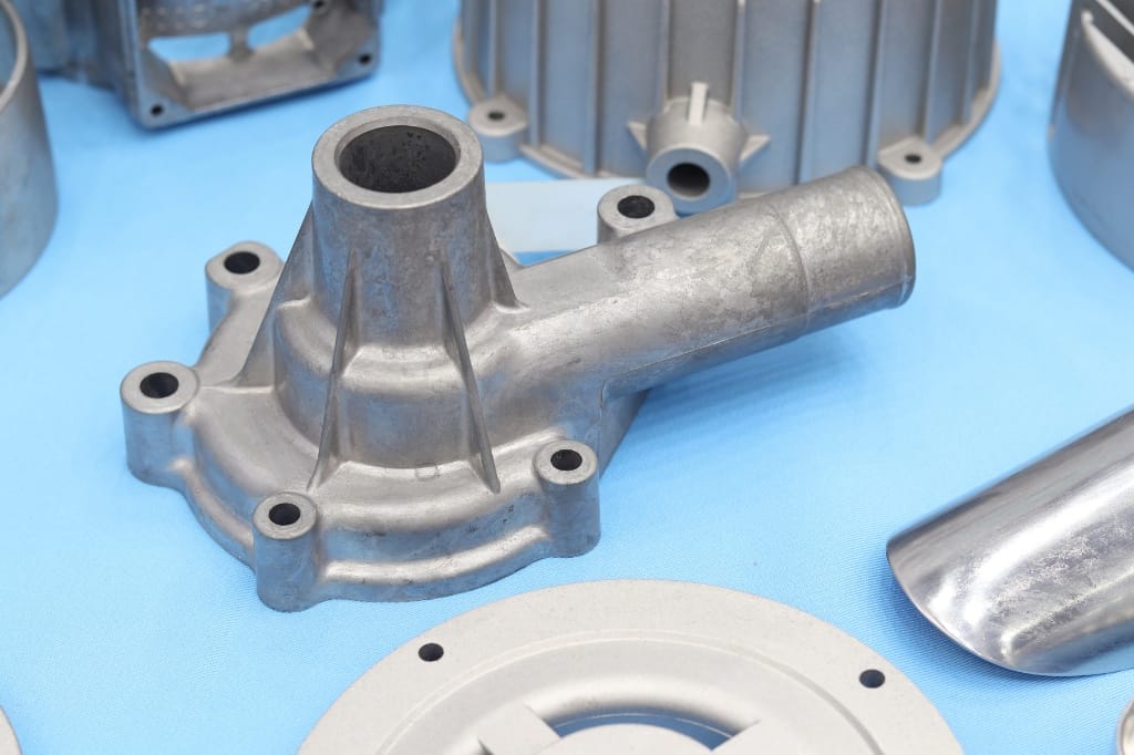
Thread size charts are standardized reference guides that document the precise specifications of threaded fasteners across different measurement systems. These charts are critical for CNC machining operations because they ensure proper thread compatibility, prevent component failure, and maintain manufacturing quality standards. Accurate thread specifications directly impact the structural integrity, assembly efficiency, and long-term performance of machined parts.
At Yijin Hardware, our CNC machining services China rely on comprehensive thread knowledge to produce precision components with exact thread sizes that meet international standards.
What are the Main Types of Thread Standards used Worldwide?
The main thread standards used globally include ISO metric threads, Unified Thread Standard (UTS), British Standard Whitworth (BSW), and specialized standards like ACME and NPT thread size chart specifications. ISO metric thread specifications dominate global manufacturing with approximately 70% market share and are controlled by ISO standards 68-1, 261, and 724. Unified Thread Standard (UTS) is predominantly used in the United States and Canada, while BSW was the first standardized thread system developed in 1841 by Sir Joseph Whitworth.
According to ISO, the diameter of a bolt can be modeled as a normal distribution with an average (mean) of 15 mm and a standard deviation of 0.1 mm. This means most bolts produced will have diameters close to 15 mm, with only small variations around this value (according to ISO 3534-2:2006).
These standards differ primarily in thread angle, pitch measurement systems, and dimensional specifications to serve various industrial applications.
| Thread Standard | Thread Angle | Designation Example | Primary Usage |
|---|---|---|---|
| ISO metric | 60° | M10×1.5 | General manufacturing |
| Unified (UTS) | 60° | 1/4″-20 UNC | Bolts and screws |
| Whitworth (BSW) | 55° | 1/2″ BSW | Pipeline components |
| ACME | 29° | 1″-5 ACME | Motion control, jacks |
How do Metric Thread Standards Work?
Metric thread standards use the “M” designation followed by the nominal diameter in millimeters and the pitch in millimeters. M10×1.5 indicates a metric thread with 10 mm major diameter and 1.5 mm pitch between thread crests. Metric threads feature a symmetrical 60° thread angle and a thread depth of 0.614 × pitch, with coarse threads being the default specification when no pitch is indicated.
These standardized specifications ensure global compatibility and are defined in ISO standards 68-1, 261, and 724, making them the most commonly used thread system in manufacturing worldwide.
What are the Critical Dimensional Parameters of Metric Threads?
The critical dimensional parameters of metric threads include major diameter, minor diameter, pitch diameter, and thread pitch. The major diameter represents the largest diameter of an external thread, measured across the thread crests. The minor diameter is the smallest diameter, measured at the thread roots. The pitch diameter is the theoretical median diameter where thread width equals groove width.
These parameters must be manufactured within specific tolerance ranges to ensure proper thread engagement and functional performance.
Metric Thread Sizes Chart
| Size | Pitch | Major Diameter | Pitch Diameter | Minor Diameter | |||
|---|---|---|---|---|---|---|---|
| Max | Min | Max | Min | Max | Min | ||
| M1.6×0.3 | 0.3 | 1.582 | 1.507 | 1.387 | 1.342 | 1.257 | 1.157 |
| M1.8×0.2 | 0.2 | 1.783 | 1.727 | 1.653 | 1.603 | 1.566 | 1.480 |
| M2×0.4 | 0.4 | 1.981 | 1.886 | 1.721 | 1.654 | 1.548 | 1.408 |
| M2.5×0.45 | 0.45 | 2.480 | 2.380 | 2.188 | 2.117 | 1.999 | 1.840 |
| M3×0.5 | 0.5 | 2.980 | 2.874 | 2.655 | 2.580 | 2.439 | 2.272 |
| M3.5×0.6 | 0.6 | 3.479 | 3.354 | 3.089 | 3.004 | 2.829 | 2.635 |
| M4×0.7 | 0.7 | 3.978 | 3.838 | 3.523 | 3.433 | 3.220 | 3.002 |
| M5×0.8 | 0.8 | 4.976 | 4.826 | 4.456 | 4.361 | 4.110 | 3.869 |
| M6×1 | 1 | 5.974 | 5.794 | 5.324 | 5.212 | 4.891 | 4.596 |
| M6×0.75 | 0.75 | 5.978 | 5.838 | 5.491 | 5.391 | 5.156 | 4.929 |
| M7×1 | 1 | 6.974 | 6.794 | 6.324 | 6.212 | 5.891 | 5.596 |
| M8×1 | 1 | 7.974 | 7.794 | 7.324 | 7.212 | 6.891 | 6.596 |
| M9×1 | 1 | 8.974 | 8.794 | 8.324 | 8.212 | 7.891 | 7.596 |
| M10×1 | 1 | 9.974 | 9.794 | 9.324 | 9.212 | 8.891 | 8.596 |
| M11×1 | 1 | 10.974 | 10.794 | 10.324 | 10.212 | 9.891 | 9.596 |
| M12×1 | 1 | 11.974 | 11.794 | 11.324 | 11.206 | 10.891 | 10.590 |
| M14×1 | 1 | 13.974 | 13.794 | 13.324 | 13.206 | 12.891 | 12.590 |
| M15×1 | 1 | 14.974 | 14.794 | 14.324 | 14.206 | 13.891 | 13.590 |
| M16×1 | 1 | 15.974 | 15.794 | 15.324 | 15.206 | 14.891 | 14.590 |
| M17×1 | 1 | 16.974 | 16.794 | 16.324 | 16.206 | 15.891 | 15.590 |
| M18×2 | 2 | 17.962 | 17.682 | 16.663 | 16.503 | 15.797 | 15.271 |
| M18×1.5 | 1.5 | 17.968 | 17.732 | 16.994 | 16.854 | 16.344 | 15.930 |
| M18×1 | 1 | 17.974 | 17.794 | 17.324 | 17.206 | 16.891 | 16.590 |
| M18×0.5 | 0.5 | 17.980 | 17.874 | 17.655 | 17.565 | 17.439 | 17.257 |
What’s the Difference Between Metric Coarse and Fine Threads?
Metric coarse threads have a larger pitch compared to fine threads of the same diameter, making them the default choice for general applications. Coarse threads (like M10×1.5) provide faster assembly, better resistance to cross-threading, and superior performance in softer materials due to their deeper thread engagement. Fine threads (like M10×1.25) feature a smaller distance between threads, offering greater tensile strength, better adjustment precision, and superior vibration resistance.
The choice between coarse and fine thread types depends on the specific application requirements, with fine threads typically preferred for precision applications and high-stress environments.
What are Unified Thread Standards (UTS)?
Unified Thread Standards (UTS) are the predominant thread system used in the United States and Canada, controlled by ASME/ANSI B1.1 standard. These screw thread specifications feature a 60° thread angle (same as metric) but use inch-based measurements with thread count specified as number of threads per inch (TPI). The main UTS variants include Unified National Coarse (UNC) and Unified National Fine (UNF), with designations like 1/4″-20 UNC indicating a 1/4 inch diameter with 20 threads per inch.
UTS threads were developed as a compromise to unify American, British, and Canadian standards and remain the primary system for bolt thread size chart specifications in North America.
How do UNC And UNF Threads Compare?
UNC (Unified National Coarse) threads have fewer threads per inch than UNF threads of the same diameter, making them ideal for general-purpose applications. UNC threads provide faster assembly, resist cross-threading better, and accommodate thicker plating and coatings due to their larger thread allowances. UNF (Unified National Fine) threads offer greater tensile strength due to their larger stress area and superior shear strength from their larger minor diameter.
Fine threads also require less torque to develop equivalent bolt preloads and have less tendency to loosen due to their smaller thread incline, making them preferred for precision applications requiring high fastener strength.
Diameter/Pitch of Commonly Used Metric Coarse Threads
| Nominal Size | Thread per inch | Major Diameter | Pitch Diameter | Minor Diameter |
|---|---|---|---|---|
| #1 | 64 | 0.073 | 0.063 | 0.056 |
| #2 | 56 | 0.086 | 0.074 | 0.067 |
| #3 | 48 | 0.099 | 0.086 | 0.076 |
| #4 | 40 | 0.112 | 0.096 | 0.085 |
| #5 | 40 | 0.125 | 0.109 | 0.098 |
| #6 | 32 | 0.138 | 0.118 | 0.104 |
| #8 | 32 | 0.164 | 0.144 | 0.130 |
| #10 | 24 | 0.190 | 0.163 | 0.145 |
| #12 | 24 | 0.216 | 0.189 | 0.171 |
| 1/4 | 20 | 0.250 | 0.218 | 0.196 |
| 5/16 | 18 | 0.313 | 0.276 | 0.252 |
| 3/8 | 16 | 0.375 | 0.334 | 0.307 |
| 7/16 | 14 | 0.438 | 0.391 | 0.360 |
| 1/2 | 13 | 0.500 | 0.450 | 0.417 |
| 9/16 | 12 | 0.563 | 0.508 | 0.472 |
| 5/8 | 11 | 0.625 | 0.566 | 0.527 |
| 3/4 | 10 | 0.750 | 0.685 | 0.642 |
| 7/8 | 9 | 0.875 | 0.803 | 0.755 |
| 1 | 8 | 1.000 | 0.919 | 0.865 |
| 1 1/8 | 7 | 1.125 | 1.032 | 0.941 |
| 1 1/4 | 7 | 1.250 | 1.157 | 1.095 |
| 1 3/8 | 6 | 1.375 | 1.267 | 1.195 |
| 1 1/2 | 6 | 1.500 | 1.392 | 1.320 |
| 1 3/4 | 5 | 1.750 | 1.620 | 1.534 |
| 2 | 4 1/2 | 2.000 | 1.856 | 1.759 |
| 2 1/4 | 4 1/2 | 2.250 | 2.106 | 2.009 |
| 2 1/2 | 4 | 2.500 | 2.338 | 2.229 |
| 2 3/4 | 4 | 2.750 | 2.588 | 2.479 |
| 3 | 4 | 3.000 | 2.838 | 2.729 |
| 3 1/4 | 4 | 3.250 | 3.088 | 2.979 |
| 3 1/2 | 4 | 3.500 | 3.338 | 3.229 |
| 3 3/4 | 4 | 3.750 | 3.588 | 3.479 |
| 4 | 4 | 4.000 | 3.838 | 3.729 |
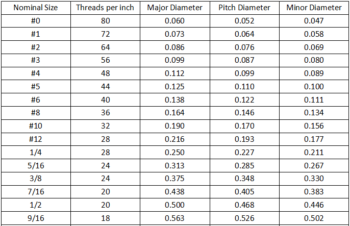
Diameter/Pitch of Commonly Used Metric Fine Pitch Threads
| Nominal Size | Threads per inch | Major Diameter | Pitch Diameter | Minor Diameter |
|---|---|---|---|---|
| #0 | 80 | 0.060 | 0.052 | 0.047 |
| #1 | 72 | 0.073 | 0.064 | 0.058 |
| #2 | 64 | 0.086 | 0.076 | 0.069 |
| #3 | 56 | 0.099 | 0.087 | 0.080 |
| #4 | 48 | 0.112 | 0.099 | 0.089 |
| #5 | 44 | 0.125 | 0.110 | 0.100 |
| #6 | 40 | 0.138 | 0.122 | 0.111 |
| #8 | 36 | 0.164 | 0.146 | 0.134 |
| #10 | 32 | 0.190 | 0.170 | 0.156 |
| #12 | 28 | 0.216 | 0.193 | 0.177 |
| 1/4 | 28 | 0.250 | 0.227 | 0.211 |
| 5/16 | 24 | 0.313 | 0.285 | 0.267 |
| 3/8 | 24 | 0.375 | 0.348 | 0.330 |
| 7/16 | 20 | 0.438 | 0.405 | 0.383 |
| 1/2 | 20 | 0.500 | 0.468 | 0.446 |
| 9/16 | 18 | 0.563 | 0.526 | 0.502 |
| 5/8 | 18 | 0.625 | 0.589 | 0.565 |
| 3/4 | 16 | 0.750 | 0.709 | 0.682 |
| 7/8 | 14 | 0.875 | 0.829 | 0.798 |
| 1 | 14 | 1.000 | 0.946 | 0.903 |
| 1 1/8 | 12 | 1.125 | 1.071 | 1.035 |
| 1 1/4 | 12 | 1.250 | 1.196 | 1.160 |
| 1 3/8 | 12 | 1.375 | 1.321 | 1.285 |
| 1 1/2 | 12 | 1.500 | 1.446 | 1.410 |
What are Thread Classes and How do they Impact Performance?
Thread classes define the acceptable tolerance range and fit between mating threads, directly impacting assembly characteristics and performance. In the UTS system, three primary class designations exist: Class 1 (loose fit), Class 2 (medium fit), and Class 3 (tight fit), with suffixes “A” for external and “B” for internal threads. Class 2 threads (2A/2B) represent the optimum thread fit for nearly 90% of commercial and industrial fasteners due to their balanced cost/performance ratio.
Thread class selection significantly influences assembly ease, manufacturing costs, and the ability to handle adverse conditions such as contamination or corrosion.
| Thread Class | Tolerance Type | Primary Applications | Manufacturing Considerations |
|---|---|---|---|
| 1A/1B | Extremely loose | Quick assembly, field repairs | Lowest precision required |
| 2A/2B | Standard commercial | General purpose applications | Balanced cost/performance |
| 3A/3B | Precision fit | Safety-critical systems, aerospace | Requires high-precision machining |
How do you Identify Threads Correctly?
Thread identification requires measuring three key parameters: major diameter, pitch (or threads per inch), and thread system. For metric threads, measure the outer diameter in millimeters and count the distance between threads. For imperial threads, measure the diameter in inches and count the number of thread crests within a one-inch length to determine threads per inch (TPI).
Thread gauges, calipers, and thread pitch chart references to provide the most accurate identification methods, with go/no-go gauges being the industry standard for verifying thread pitch diameter compliance.
What are the Most Reliable Thread Measurement Methods?
The most reliable thread measurement methods include using thread ring gauges for external threads and thread plug gauges for internal threads. These gauges provide a direct functional verification of thread dimensions and are manufactured to precise measurement specifications. For more detailed analysis, a micrometer is used to measure thread pitch diameter precisely, while optical comparators allow visual inspection of thread profiles.
For CNC machining verification, coordinate measuring machines (CMMs) equipped with thread measurement software provide comprehensive dimensional analysis to ensure compatibility of all thread parameters.
What Factors Should You Consider when Selecting Thread Types for CNC Machining?
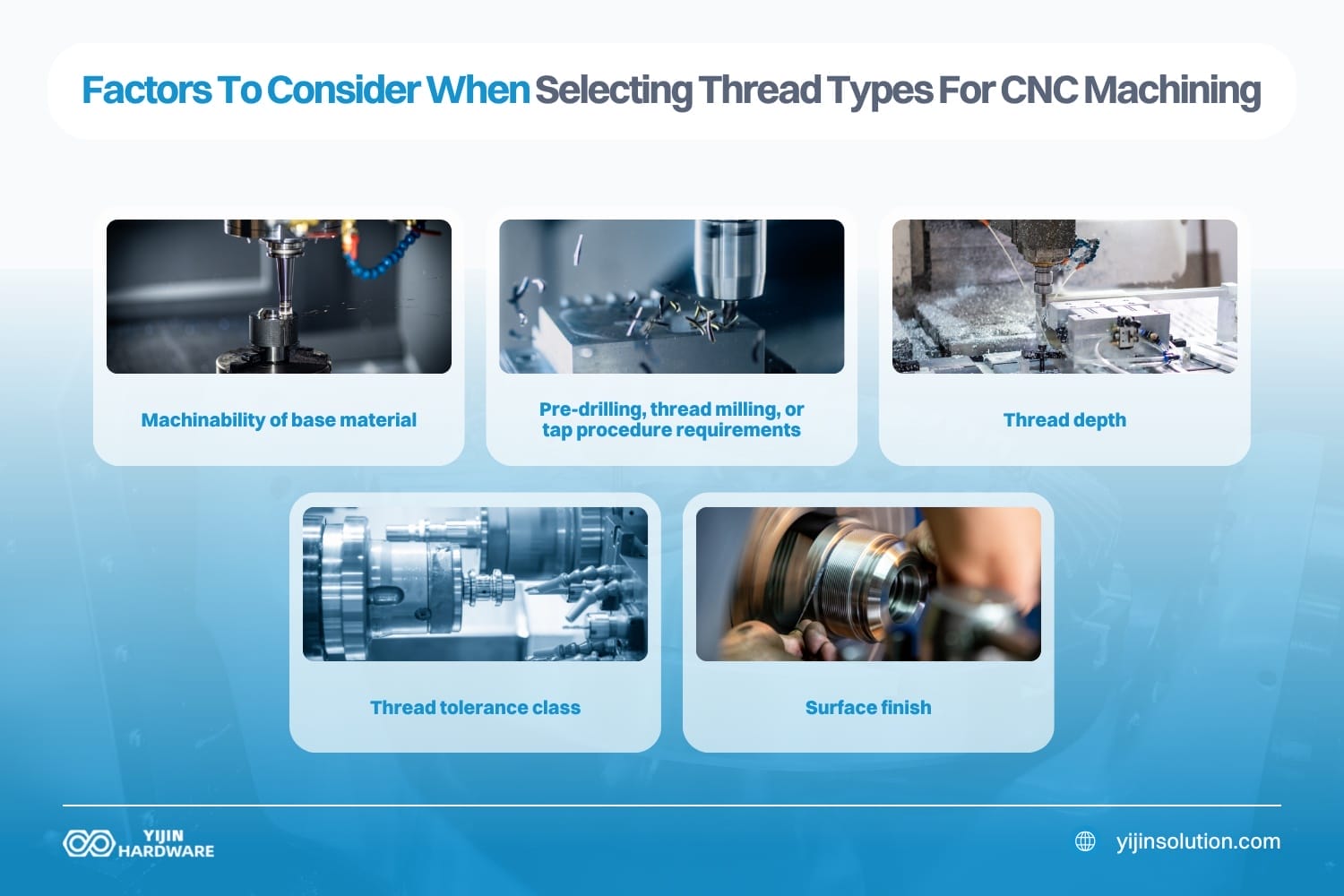
Thread selection should consider application requirements, material properties, environmental conditions, and manufacturing methods. Application factors include load direction, vibration exposure, and adjustment precision needs. Material factors impact thread strength, with softer materials typically benefiting from coarse threads while harder materials might require fine threads. Environmental conditions like temperature fluctuations and corrosion exposure influence thread systems and material choices.
For CNC machining specifically, consider these additional factors:
- Machinability of the base material affects thread quality and tool wear
- Internal threads typically require pre-drilling and may need thread milling or tap procedures
- Thread depth affects the machining approach (through-hole vs. blind hole considerations)
- Thread tolerance class determines machining precision requirements
- Surface finish specifications impact machining parameters and tool selection
How do British Standard Threads Differ from other Systems?
British Standard Whitworth (BSW) threads differ from metric and unified threads by using a 55° thread angle instead of 60°, and featuring rounded roots and crests. Developed by Sir Joseph Whitworth in 1841, BSW was the first standardized thread system and offers excellent strength and grip due to its profile design. BSW threads are designated by diameter in inches and threads per inch (e.g., 1/2″ BSW).
While largely replaced by metric threads in most applications, BSW threads still see use in certain legacy systems and specific applications like marine and pipeline fittings in Europe, making them an important consideration for replacement parts manufacturing.
Yijin Hardware | Your Advanced Thread Machining Partner
Proper thread selection and specification are critical elements in successful CNC machining and component engineering. By understanding the distinctions between thread standards, classes, and applications, engineers can make informed decisions that optimize component performance and assembly characteristics.
At Yijin Hardware, our expertise in thread machining spans all major international standards, with our precision CNC capabilities ensuring exact thread production regardless of complexity or specification. Whether your project requires metric, unified, or specialized thread systems, our technical knowledge and advanced machining capabilities deliver threaded components that meet or exceed your exact requirements. Contact us for CNC machining services.
Thread Size Chart FAQs
When should you use specialized thread types like ACME or NPT?
ACME threads should be used specifically for power transmission and motion control applications due to their trapezoidal 29° thread profile that efficiently transfers force and resists contamination. National Pipe Thread (NPT) should be used exclusively for pipe connections requiring a pressure-tight seal, with their 1:16 taper rate creating an interference fit as the threads are tightened. Neither ACME nor standard threads should be substituted for NPT in pressure applications, as they lack the sealing capability required for fluid or gas containment.
How do thread manufacturing methods impact thread performance?
Thread manufacturing methods significantly impact thread performance, with the three primary methods being cutting, rolling, and grinding. Thread cutting produces precise threads through material removal but can create stress concentration points at thread roots. Thread rolling creates stronger threads by cold-forming the material, which preserves grain structure and work-hardens the surface, increasing fatigue resistance by up to 30% compared to cut threads.
What are the special considerations for CNC machining threads in different materials?
Different materials require specific CNC machining approaches to produce high-quality threads. Aluminum allows fast cutting speeds, but may require lubricant to prevent chip buildup and tool binding. Stainless steel demands slower cutting speeds, rigid tool support, and proper lubricant to dissipate heat and prevent work hardening. Titanium requires extremely rigid tooling, specialized geometries, and consistent cutting pressure to prevent thread damage.
Back to Top: Complete Thread Size Chart Guide: Understanding All Standards and Applications