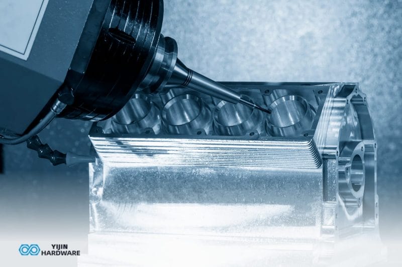

Every sheet metal part starts as flat stock. What turns it into a bracket, enclosure, or structural panel is the sheet metal fabrication equipment a shop runs. The machines themselves determine what technical parameters are achievable, how fast parts ship, and what the per-part cost looks like at different volumes on a shop floor.
For engineers specifying parts or procurement teams evaluating suppliers, the equipment a shop actually runs is a more reliable indicator of capability than marketing copy about precision or quality.
This guide covers the major equipment categories, explains how each one affects your part output, and helps you match equipment capability to your project requirements.
What is Sheet Metal Fabrication Equipment?
Sheet metal fabrication equipment is the category of machines used to cut, form, join, and finish flat metal stock into precision components. The term covers individual machines like laser cutters and press brakes, as well as integrated automated lines that handle multiple operations in sequence.
These machines produce parts with controlled tolerances, consistent surface finish, and process-appropriate repeatability. Achievable tolerance and output quality depend on both the machine type and the variables that govern it, including material, sheet thickness, calibration state, and part geometry.
Sheet Metal Fabrication Equipment List: Quick Reference
The table below provides a buyer-oriented overview of the major equipment types.
| Equipement | Fonction principale | Automation Level | Industries typiques |
|---|---|---|---|
| Laser Cutting Machine | Precision thermal cutting of sheet and plate | High, CNC + auto sheet loading | Aerospace, automotive, electronics |
| Press Brake | Bending sheet into angles and forms | Medium to high, CNC or robotic cell | Enclosures, brackets, HVAC |
| Punch Press / Turret Punch | Hole punching, forming, and blanking | High, CNC turret | Electronics, telecom, panels |
| Plasma Cutter | Thermal cutting of thick conductive plate | Medium to high, CNC table | Structural, heavy equipment |
| Waterjet Cutter | Cold cutting with no heat-affected zone | High, CNC | Aerospace, medical, composites |
| MIG/TIG Welding Station | Joining sheet metal components | Manual to robotic | Automotive, structural, medical |
| Metal Shear / Guillotine | Straight-line cutting of sheet stock | Manual to CNC | General fabrication, blanking |
| Roll Former / Coil Line | Continuous forming of long profiles | High, coil-fed automated | Construction, HVAC, automotive |
| Spot Welder | Resistance joining of thin overlapping sheets | Manual to robotic | Automotive body panels, enclosures |
| Deburring / Finishing Machine | Edge smoothing and surface treatment | Semi-automatic to automated | All sectors requiring finished edges |
Laser cutters, CNC press brakes, and welding stations form the baseline equipment set in most general fabrication facilities. Punch presses and plasma cutters extend capability into high-volume blanking and thick-plate work. Roll formers and automated finishing equipment are add ons for shops that serve high-volume or specialized markets.
How does Equipment Choice Affect Part Output?
The same machine can produce very different outputs depending on how it is set up, what material it is processing, and what the part geometry requires. Equipment specifications describe an overarching capability, not the output a buyer will receive on a specific part.
Achievable tolerance
Tolerance on a finished sheet metal part is not a fixed number tied to the machine model. It depends on the material type and thickness, the machine’s calibration state, part geometry complexity, and the number of operations in the process chain.
A fiber laser cutting a simple rectangular blank from 1 mm mild steel will hold tighter dimensions than the same laser cutting a complex profile from 6 mm stainless steel . Tolerance figures cited for any equipment type are indicative ranges, not guarantees for a specific part.
Edge quality and surface finish
Edge quality is determined by the process type, the material being cut, cutting speed, and any secondary finishing operations specified. A laser-cut edge on thin steel can be weld-ready straight off the machine. A plasma-cut edge on a 20 mm plate typically needs grinding before downstream operations. Buyers who specify surface finish requirements should confirm them during the DFM review, not after the first article inspection arrives.
How production volume changes the economics
Equipment choice is also a volume decision. A fiber laser is efficient across a wide volume range, from prototypes to production runs of thousands. A robotic press brake cell only justifies its capital cost above a certain threshold.
Roll forming is economical only at high volume where tooling investment can be spread across a long run. The right equipment for a prototype is not always right for the production run, and your fabrication partner should be able to advise on when to shift.
Lead time drivers
Lead time is determined by more than equipment speed. Setup time between jobs, material procurement, queue depth at the shop, number of operations in the process chain, and secondary finishing all contribute.
A shop with a fast laser but a two-week queue delivers slower than a shop with a slightly slower machine and open capacity. Lead time estimates should reflect the entire process chain, not just the cycle time for a single operation.
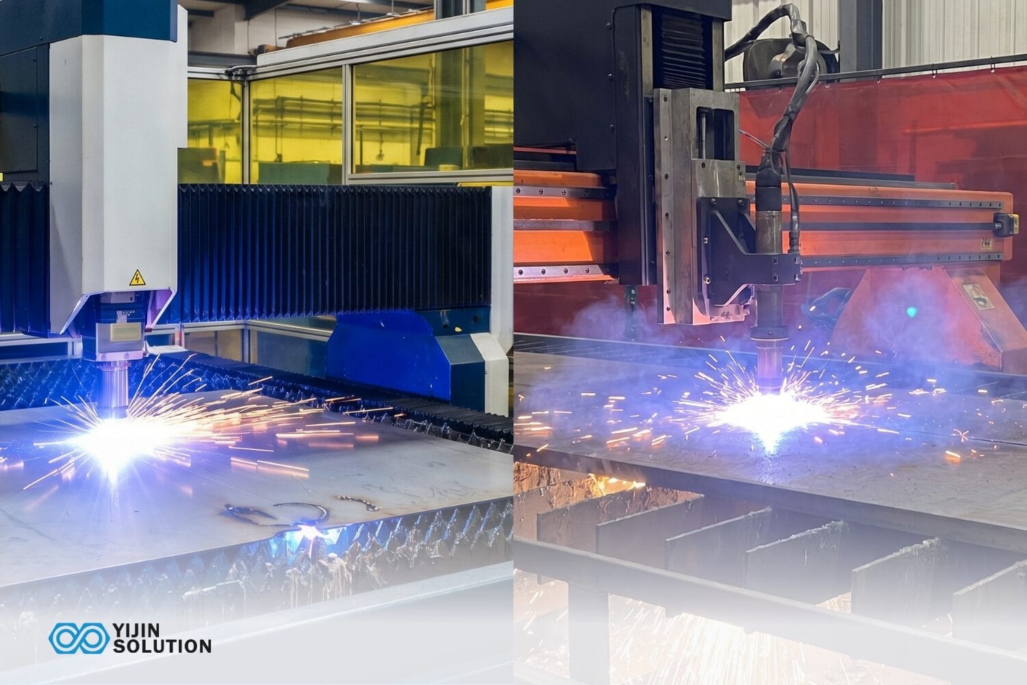
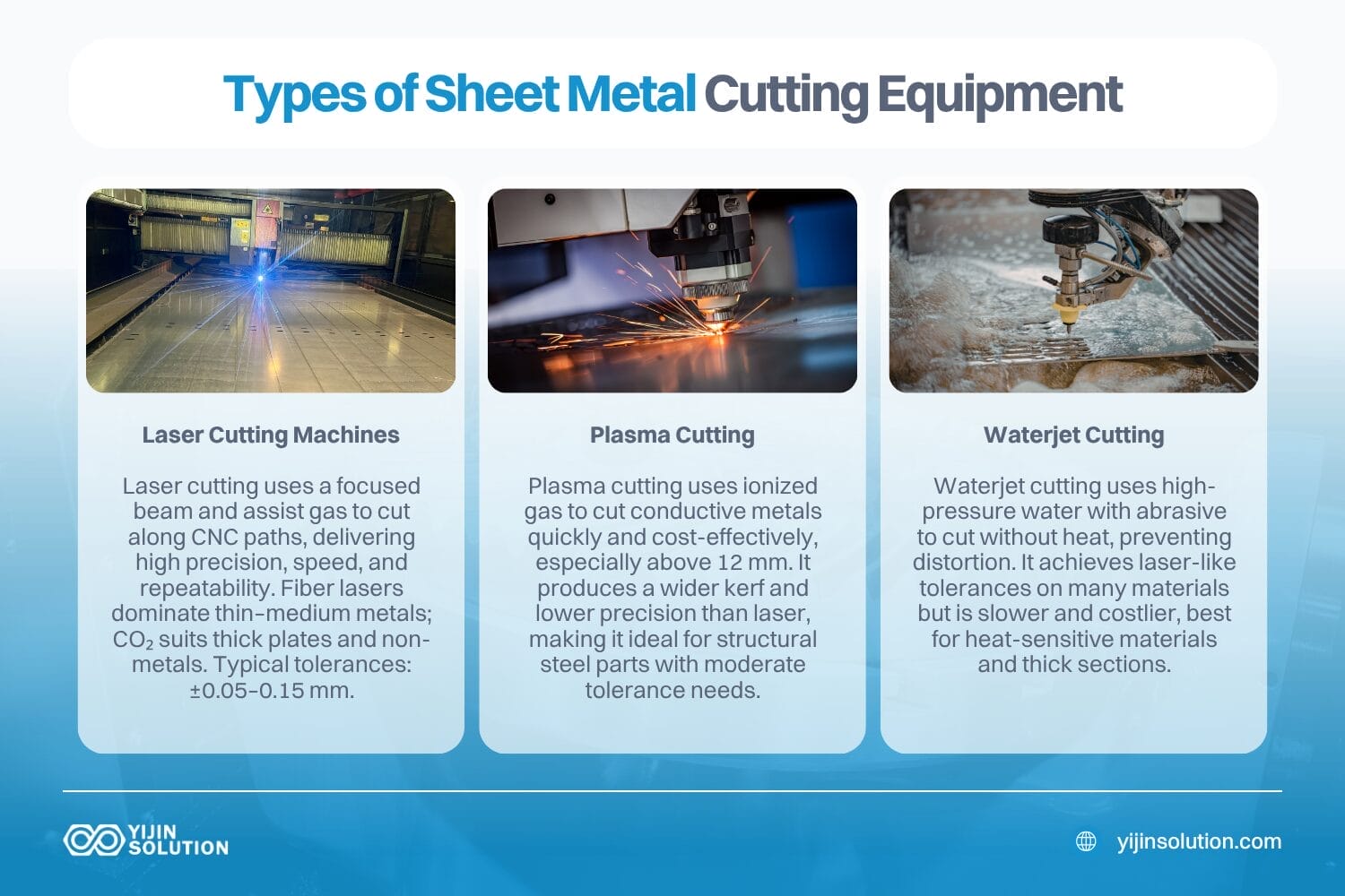
Sheet Metal Cutting Equipment: Laser, Plasma & Waterjet
Laser cutting machines
Laser cutting uses a focused beam to melt or vaporize material along a CNC-programmed path, with an assist gas clearing molten material from the kerf. It is the most widely used cutting process in custom sheet metal fabrication.
Two laser types dominate the market. Fiber lasers operate at a 1.06 μm wavelength that is absorbed efficiently by metals, making them the standard in most modern fabrication shops for thin-to-medium sheet. CO2 lasers, operating at 10.6 μm, retain advantages for thick steel plates above 20 mm and for non-metallic materials like acrylic and wood. A third category, Nd:YAG and disk lasers, serves niche precision applications but is less common in general fabrication.
Laser cutting on sheet metal achieves tolerances in the ±0.05 to 0.15 mm range, depending on material type, sheet thickness, machine calibration, assist gas selection, and part geometry. Thinner sheets and simpler profiles generally allow tighter results. Thicker material or complex geometry shifts the range wider.
Laser type comparison:
| Type de laser | Typical Power Range | Best Material Match | Key Trade-off |
|---|---|---|---|
| Fibre | 1 to 40 kW | Metals: steel, stainless steel, aluminum, copper, brass | Faster on thin-to-medium sheet; edge quality can degrade on thick plate |
| CO2 | 1 to 6 kW | Non-metals, thick steel plate above 20 mm | Slower on thin metal; higher operating cost; superior thick-plate edge quality |
| Nd:YAG / Disk | 0.5 to 6 kW | Specialty metals, micro-cutting, 3D cutting | Higher equipment cost; used for niche precision work |
Fiber lasers now account for approximately 60% of the laser cutting market. Most new fabrication shops targeting sheet metal work install fiber systems as their primary cutting platform. CO2 machines remain relevant for shops that process a mix of metals and non-metals, or that specialize in heavy plates.
Découpe au plasma
Plasma cutting uses ionized gas to cut electrically conductive metals. It is faster and more economical than laser for thick plate above 12 mm, but produces a wider kerf and lower dimensional precision. High-definition, or HD, plasma narrows the tolerance gap with laser on thicker plates, but does not match laser on thin sheet.
Plasma fits into the buyer’s decision where the application involves heavy structural work, such as carbon steel plates. It is also the right choice for situations where the part’s tolerance requirement is compatible with plasma’s achievable range. For structural steel brackets, frames, and gussets cut from 12 to 50 mm plates, plasma is often the more cost-effective process.
Découpe au jet d'eau
Waterjet cutting is a cold-cutting process. High-pressure water mixed with abrasive garnet cuts material without generating a heat-affected zone, which suits heat-sensitive materials, composites, and thick plates where thermal distortion is unacceptable.
Waterjet cutting achieves tolerances comparable to lasers on many materials, though actual results depend on material type, thickness, and cutting speed. Slower cutting speeds generally allow tighter tolerance. The trade-off is cycle time and operating cost: waterjet is slower and more expensive per part than laser for standard steel sheet. It is most cost-effective on heat-sensitive materials where thermal input would cause distortion or metallurgical change.
Cutting process comparison table
The table below is an advisory selection reference, not a performance guarantee. Achievable results depend on the specific equipment, material, and setup.
| Processus | Typical Tolerance Range* | Max Thickness | Edge Quality | Coût de la mise en place | Meilleure application |
|---|---|---|---|---|---|
| Laser | ±0.05 to 0.15 mm | 25 mm mild steel, 15 mm stainless on 6 kW fiber | Clean, often weld-ready | Faible à modéré | Precision sheet metal parts, from prototypes to production |
| Plasma | ±0.5 to 1.5 mm, tighter with HD | 50+ mm conductive metals | Rougher, may need grinding | Faible | Thick structural plate, carbon steel |
| Jet d'eau | ±0.05 to 0.15 mm at slow speed | 150+ mm on some materials | Smooth, no HAZ | Moderate to high | Heat-sensitive materials, composites, thick plate |
| Punch Press | ±0.05 to 0.10 mm | 6 mm typical | Clean, formed edges | Moderate, tooling-dependent | High-volume hole patterns, blanking |
Tolerance ranges shown are indicative. Achievable tolerances depend on material, sheet thickness, machine calibration, part geometry, and process setup. Confirm specific requirements with your fabrication partner.
Sheet Metal Forming Equipment: Press Brakes and Roll Formers
Press brakes
A press brake bends sheet metal between a punch and die to a precise angle. It is the central forming machine in any sheet metal shop, and the type of press brake a shop runs directly affects bend accuracy, repeatability, and throughput.
Four main types serve different production scenarios. Manual press brakes suit simple bends in low volumes. Hydraulic CNC press brakes deliver programmable precision with high tonnage capacity, making them the workhorse of most fabrication shops. Electric and hybrid servo systems achieve tighter repeat accuracy and use up to 50% less energy than hydraulic models, ideal for precision work on thinner sheets. Robotic press brake cells combine a CNC press brake with robotic loading and unloading for lights-out production at volume.
Modern CNC hydraulic press brakes hold bend angle tolerance of approximately ±0.5° under standard conditions. Servo-electric systems achieve tighter repeat accuracy. Actual results depend on material type and thickness, tooling condition, back gauge calibration, and bend sequence. Springback behavior varies significantly across materials: aluminum springs back more than mild steel at the same thickness, and high-strength steels introduce their own complexities.
Press brake type comparison:
| Press Brake Type | How It Works | Meilleur pour | Trade-off |
|---|---|---|---|
| Manual | Operator-controlled ram with manual back gauge | Simple bends, low volume, short runs | Accuracy depends entirely on the operator skill |
| Hydraulic CNC | CNC-controlled hydraulic ram with a programmable back gauge | General fabrication, medium to high volume | Requires hydraulic fluid maintenance; thermal drift over long runs |
| Electric / Hybrid | Servo motor-driven ram via ball screw or roller screw | Precision bending, thin sheet, energy-sensitive shops | Lower tonnage capacity than large hydraulic systems |
| Robotic Cell | CNC press brake with robotic material handling | High-volume production, lights-out manufacturing | Higher capital investment, requires consistent blank sizes |
For most custom fabrication work, a CNC hydraulic press brake covers the widest range of applications. Servo-electric systems are worth evaluating for shops that prioritize precision on thin-gauge work or need to reduce energy costs. Robotic cells suit production environments where volume justifies the capital investment.
Roll formers and coil lines
Roll forming bends flat sheet or coil stock through a series of roller dies to produce long, uniform profiles. Channel, angle, tube, and custom profiles for construction, automotive, and HVAC applications are the typical outputs.
Roll forming becomes cost-effective at high volumes where tooling investment is amortized across a long production run. It is not suited for low-volume custom work. For buyers evaluating a fabrication partner, roll forming capability signals a shop that can handle high-volume profile production, but it is rarely the deciding factor for custom sheet metal parts.
Sheet Metal Joining Equipment: Welding and Fastening Systems
MIG and TIG welding
MIG welding, or Gas Metal Arc Welding, uses a continuously fed wire electrode. It is faster than TIG and suited for thicker material and structural joints. The cosmetic finish is lower than TIG, which is why MIG is standard in high-volume automotive and structural fabrication, including robotic MIG cells.
TIG welding, or Gas Tungsten Arc Welding, produces a precise, clean weld bead. It is preferred for thin sheet, stainless steel, aluminum, and cosmetically visible joints. Robotic TIG cells serve precision aerospace and medical applications where weld quality is inspected and documented.
Welding method selection affects part distortion as much as joint strength, particularly on thin sheets. TIG’s lower heat input reduces distortion on thin stainless panels, but adds cycle time. The right welding method should be confirmed during the DFM review based on the part’s material, thickness, joint requirements, and cosmetic specification.
Spot welding and resistance welding
Resistance spot welding joins thin sheet panels at specific points using heat generated by electrical resistance. No filler material is required. Fast cycle time and low consumable cost make it the dominant joining method for automotive body panels, enclosures, and brackets at volume.
The limitation is scope: spot welding suits thin, overlapping sheets, not structural joints or thick material. Weld point location affects part stiffness distribution, which should be considered at the design stage rather than left to the production floor.
Sheet Metal Finishing Equipment
Finishing equipment handles the last step before inspection and shipment: removing burrs, breaking sharp edges, and preparing surfaces for coating or assembly. Unlike cutting and forming, finishing is often invisible in the spec sheet but becomes visible the moment a painted part shows edge failures or an assembler cuts a hand on an unprocessed edge.
Deburring and finishing machines
Deburring and finishing equipment removes the sharp edges, slag, and heat-affected residue left behind by cutting and punching operations. The output is a part with consistent edge quality, safe handling, and a surface ready for paint, powder coat, or downstream assembly. For any part that contacts an operator, mates with another component, or goes through a coating line, finishing is a required step in the process chain.
Several machine types cover different requirements:
- Wide-belt deburring machines pass flat sheets through abrasive belts and brushes to remove burrs and slag from both sides in a single pass, making them standard in shops that run high-volume laser or punch work.
- Edge rounding machines add a controlled radius to cut edges, which is generally required for reliable powder coat adhesion on sharp corners.
- Vibratory tumblers and centrifugal barrel finishers handle smaller parts in batches, suited for brackets, hardware, and components where edge break and surface smoothing matter, but exact dimensional control is less critical.
- Robotic sanding and grinding cells handle larger or more complex geometries that cannot pass through a flat deburring line.
Automation levels range from manual bench grinders for one-off work up to fully automated in-line finishing that feeds directly off a laser or punch table. A shop that runs painted or powder-coated parts should have dedicated deburring and edge-rounding capacity, since inconsistent edges show up as coating failures downstream.
For unpainted stainless or aluminum parts where cosmetic finish matters, ask about the specific abrasive media used, as different grits and belt types produce different surface finishes on the same base material.
Automated Sheet Metal Fabrication Equipment
Automation in sheet metal fabrication means CNC-controlled equipment, robotic handling cells, and integrated systems that reduce manual intervention between operations. The category includes CNC laser and plasma tables, automated press brake cells with robotic loading, automated punch-and-form lines, and fully integrated coil-fed blanking and forming lines.
For buyers, automated sheet metal fabrication equipment delivers three outcomes: lower per-part cost at volume, improved dimensional consistency across a batch, and the ability to run lights-out production on repeat orders. These advantages matter most for high-volume runs, where consistency and throughput drive the economics.
The trade-off is capital investment. Automated lines are cost-justified above certain volume thresholds. Custom or low-volume work, which includes most prototype and short-run orders, often runs more efficiently on flexible CNC cells where setup time per job is lower.
How Equipment Choice Affects Your Part Design
The fabrication equipment itself imposes constraints on the design choices. Every point below is tied to a specific equipment type or process characteristic, not generic DFM advice.
- Minimum feature size: Laser cutting can hold internal radii down to approximately the beam kerf width on fiber systems, typically 0.1 to 0.3 mm. Punch presses need a minimum hole-to-edge distance of at least 1× material thickness. The actual minimum feature size depends on the material, thickness, and machine setup.
- Bend radius and material springback: Press brake tooling determines the minimum inside bend radius. As a baseline, the minimum inside bend radius for mild steel is approximately 1× material thickness. Aluminum typically requires a wider ratio because of greater springback. Springback behavior varies with alloy, temper, and bend direction relative to the grain. Bend radii should be confirmed with the fabrication partner during DFM review.
- Weld distortion on thin sheet: TIG welding on thin stainless steel introduces heat that can warp flat panels if the welding sequence and fixturing are not engineered into the DFM review. Distortion risk increases with panel size and decreases with an effective fixturing strategy.
- Tolerance stack-up across operations: Parts that move across multiple operations, such as cut, bend, then weld, accumulate tolerances at each step. DFM review should identify which dimensions are critical-to-function and ensure they are held in the final operation where achievable precision is highest.
- Automation compatibility: Parts designed with consistent blank sizes, symmetric geometry, and standard bend sequences are easier to run on automated press brake cells with robotic loading. This reduces cycle time and improves batch consistency.
Talk to Yijin About Your Sheet Metal Project
The right equipment choice comes down to matching process capability against tolerance, volume, material, and what happens downstream. Laser, plasma, and waterjet each have windows where they are the correct answer. Press brakes, roll formers, welding cells, and finishing equipment each add their own constraints on what the final part can be. A fabrication partner who can walk you through these trade-offs at the DFM stage will save rework, scrap, and missed delivery dates later in the program.
Yijin Solution runs laser cutting, press brakes, punching, welding, deburring, and finishing under one roof in a single facility. Our engineering team reviews every incoming part for material selection, tolerance feasibility, bend radius, weld distortion risk, and finishing requirements before quoting, so the number we send back reflects what the shop floor can actually deliver.
Upload your CAD files for a free DFM review and quote within 24 hours.
Sheet Metal Fabrication Equipment FAQs
Can different cutting processes be used on the same part?
Yes. It’s common to use laser cutting for precision features and plasma or waterjet for thicker sections of the same part, though this adds handling steps and can affect tolerance stack-up. If your part has mixed thickness zones or requires both thermal and cold cutting, raise this during the DFM review so the fabrication partner can plan the process sequence and set realistic tolerances for each section.
How do I know if my fabrication partner’s equipment is well maintained?
Ask about calibration schedules, preventive maintenance records, and whether the shop tracks machine drift over time. A CNC press brake that hasn’t been calibrated recently will produce different bend angles than the spec sheet suggests. Shops that maintain ISO 9001 or equivalent quality systems typically have documented maintenance programs, but it’s reasonable to ask directly.
Does equipment age affect part quality?
It can. Older machines may have worn guides, degraded ball screws, or outdated control software that limits positioning accuracy. However, a well-maintained older machine with recent calibration can outperform a newer machine that’s been neglected. The key indicator is whether the shop can demonstrate consistent output through inspection records, not simply the age of the equipment on the floor.
When should I switch fabrication methods between prototyping and production?
The trigger is usually volume, tolerance tightening, or cost. A laser-cut and manually bent prototype might work perfectly for five units, but at 500 units the same part could benefit from a robotic press brake cell or even a dedicated punch-and-form setup. Ask your fabrication partner to quote both approaches once your volumes are confirmed. The crossover point varies by part geometry, but the conversation should happen before production commitment, not after.
What questions should I ask a fabrication shop about their equipment?
Focus on capability match rather than brand names. Useful questions cover laser type and wattage, whether press brakes are CNC or manual, maximum sheet size and tonnage capacity, in-house welding and finishing capability, and how the shop handles tolerance verification. A shop that can walk you through how their equipment lineup maps to your specific part is more valuable than one that simply lists machines.
Retour en haut de la page : Sheet Metal Fabrication Equipment: Types, Functions & How to Choose