
When a structural aluminum part needs to be heat treated to T6, high-pressure die casting, or HPDC, is off the table. Subsurface porosity from the injection process causes blistering during solution treatment, which means the part fails before it reaches its mechanical potential.
Gravity die casting fills that specific gap: low-porosity castings, production-ready dimensional consistency, and full heat-treatment capability at medium volumes.
Au Solution Yijin, we produce gravity die castings across aluminum, zinc, magnesium, and copper alloys with in-house heat treatment, CNC machining, and CMM inspection under one roof.
This guide breaks down every cost variable, process step, and selection trade-off so you can model your project accurately and choose the right process with confidence.
What is Gravity Die Casting?
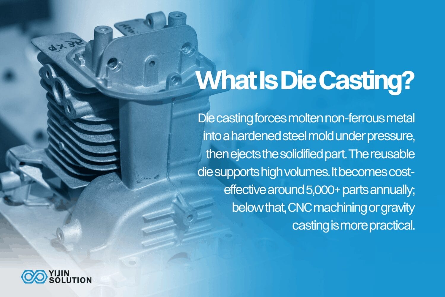
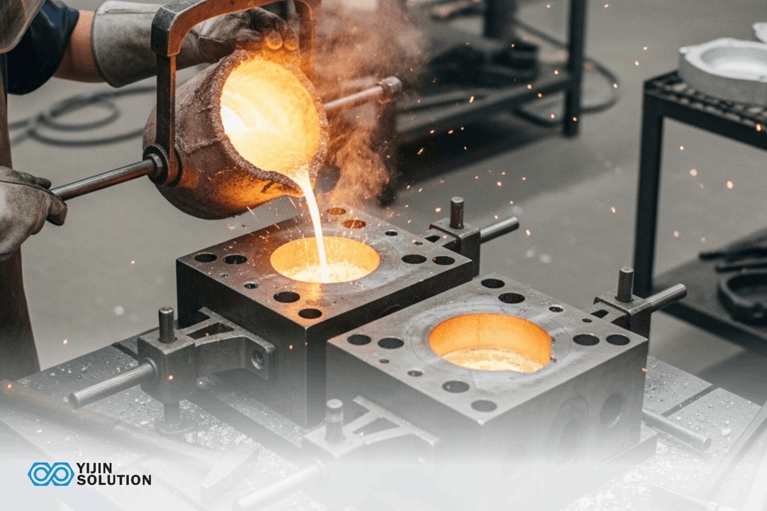
Gravity die casting, also called permanent mold casting, is a process where molten non-ferrous metal is poured into a reusable steel die under gravity head pressure alone. No external injection pressure is applied. The die is opened once the casting solidifies, and the cycle repeats.
The absence of injection pressure is what separates GDC from HPDC. Slow, gravity-driven fill reduces turbulence and air entrapment, producing a denser casting microstructure with lower porosity. That microstructure is stable enough to undergo solution treatment and aging without blister formation. This is a critical advantage for structural applications.
The Gravity Die Casting Process — Step by Step
While alloy, part geometry, and die complexity affect specific parameters, GDC follows a consistent 11-step sequence across all variants. The solidification and riser design and heat treatment steps are the quality-critical differentiators that set GDC apart from HPDC.
| Étape | Nom | Ce qui se passe | Levier de qualité clé |
|---|---|---|---|
| 1 | Préparation de la matrice | Preheat both die halves to operating temperature, typically 150–250°C for aluminum. Apply die release lubricant to prevent metal adhesion and regulate thermal gradient. | Die temperature uniformity |
| 2 | Core Setting | Insert sand or metal cores to form internal cavities and undercuts the permanent die cannot produce. Verify core seating and print-off surfaces. | Core dimensional accuracy and seating |
| 3 | Serrage de la matrice | Close and latch die halves. No hydraulic injection pressure is applied. The die only resists the static ferrostatic pressure of the molten metal head. | Die alignment and latch integrity |
| 4 | Metal Melting and Prep | Melt alloy in a reverberatory or electric resistance furnace. Degas the melt via rotary degassing, flux, and take temperature and hydrogen readings before pouring. | Melt cleanliness and hydrogen level |
| 5 | Pouring | Ladle or automatic pouring system fills the die cavity from a sprue at the top or side. | Pour rate and turbulence control |
| 6 | Solidification | Metal solidifies under gravity with no external pressure. Risers supply molten metal to compensate for volumetric shrinkage. Controlled by die temperature and riser geometry. | Riser design and thermal gradient |
| 7 | Die Opening and Ejection | Open die halves once the casting reaches ejection temperature. Eject via ejector pins or manual extraction. Remove sand cores where used. | Ejection temperature window |
| 8 | Degating | Remove runners, risers, and flash by sawing, clipping, or grinding. Returns are recycled back into the melt. | Yield and returns rate |
| 9 | Traitement thermique | For structural applications: solution treat, also known as T4 or solution treat and age, known as T6/T7, to develop full mechanical properties. | Heat treatment specification |
| 10 | L'inspection | Dimensional check via CMM or coordinate gauging. Visual and dye penetrant inspection. X-ray NDT for critical structural castings. First Article Inspection, or FAI, against drawing callouts. | FAI, CMM, and X-ray reporting |
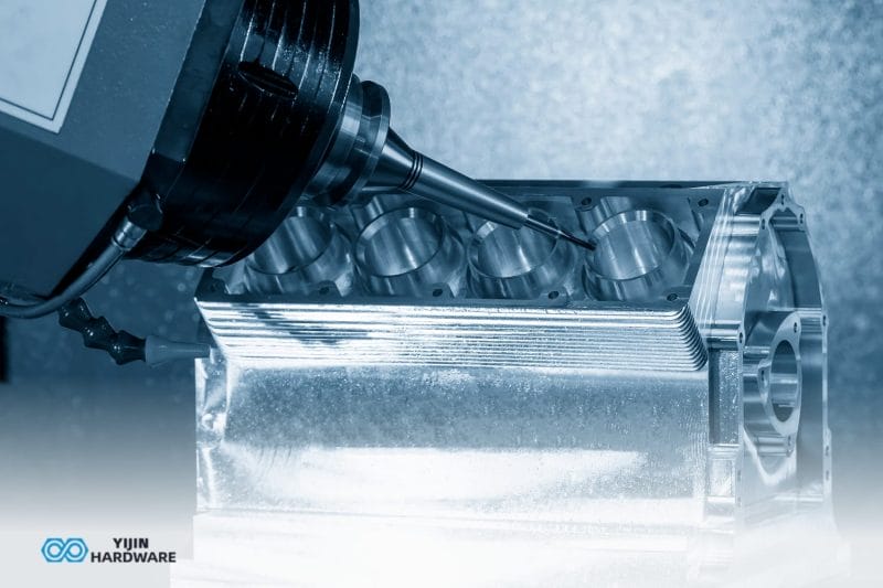
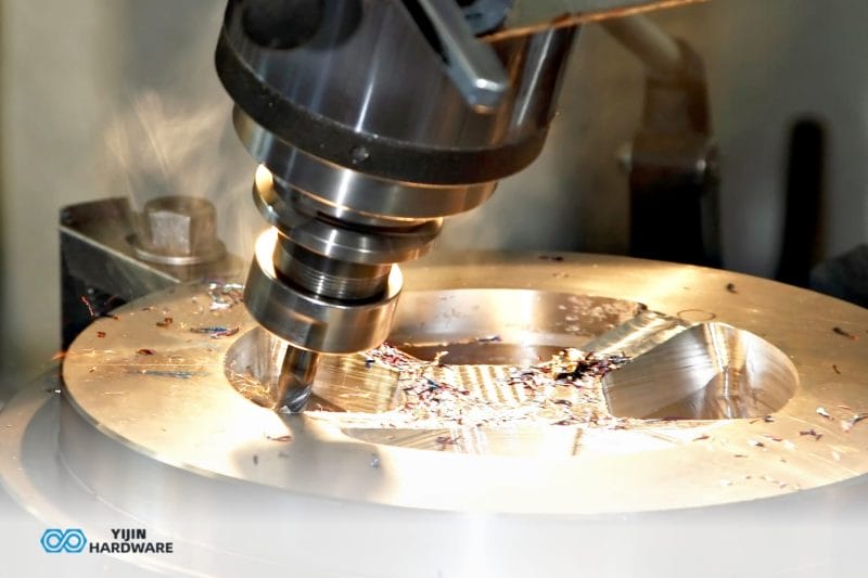
| 11 | Opérations secondaires | CNC machine tight-tolerance features such as bores, mating faces and threads. Apply surface treatments. Pressure-test where specified. | Tolerance stack-up and surface spec |
Gravity Die Casting Process Variants
Standard Gravity Die Casting: Top-Pour and Side-Pour
Molten metal is ladled into the die from the top or through a side runner. This is the most common GDC variant for aluminum and copper alloys and the lowest-cost entry point in the GDC family.
Tilt-Pour/Rotary Die Casting
The die is rotated or tilted during the pour so metal enters the cavity in a controlled, laminar flow eliminating the turbulence and oxide entrainment associated with top-pour.
Tilt-pour produces castings with the lowest porosity and highest consistency in the GDC family, making it the preferred process for safety-critical automotive structural castings such as steering knuckles, control arms, and subframe nodes.
Gravity Die Casting with Sand Cores
Where internal geometry can’t be formed by the permanent die, like in the case of blind passages and complex internal channels, removable sand cores are inserted before each shot. Sand cores add per-cycle cost of £1–£10 per core and introduce dimensional variation at the core interface, but they enable geometric complexity that a coreless die simply can’t deliver.
Gravity Die Casting vs. HPDC vs. Sand Casting — Process Comparison
Process selection for non-ferrous structural castings comes down to three variables: required mechanical properties, annual volume, and geometry constraints. The table below is a decision aid, not just a data matrix.
| Attribut | Gravity Die Casting (GDC) | High-Pressure Die Casting (HPDC) | Moulage au sable |
|---|---|---|---|
| Processus | Gravity fill into permanent steel die | High-pressure injection, about 10–175 MPa into hardened die | Gravity fill into single-use sand mold |
| Coût de l'outillage | Medium — $8,000–$40,000 | High — $15,000–$120,000+ | Low — $500–$5,000, making up the pattern cost |
| Tooling Lead Time | 8-14 semaines | 12–20 weeks | 2–6 weeks |
| Volume Sweet Spot | 1 000 à 50 000 pièces/an | 50,000–500,000+ parts/year | 1–5,000 parts/year |
| Durée du cycle | 2–5 minutes | 15–60 seconds | 15–60 minutes |
| Min Wall Thickness | 3–5 mm for Al | ~1.0 mm for Al | 3–6 mm |
| Précision dimensionnelle | ±0.3–0.5 mm as-cast | ±0.1–0.2 mm as-cast | ±0.5–1.5 mm |
| Finition de la surface | 3–6 µm | 1–3 µm | 6–25 µm |
| Porosity Level | Low — slow fill reduces entrapped air | Higher — fast injection traps air | Low–Medium |
| Heat Treatable? | Yes — T4, T6, T7 all viable | No — porosity blisters during heat treat | Oui |
| Propriétés mécaniques | Good — dense structure, heat treatable | Moderate — as-cast properties only | Good — heat treatable, isotropic |
| Meilleur pour | Structural, medium-volume, heat-treatable parts | High-volume, thin-wall, cosmetic parts | Low-volume, large, or prototype parts |
Tell us your annual volume, alloy, and key mechanical requirements. We’ll confirm which casting process delivers the best cost per part for your application.
Which Alloys are Used in Gravity Die Casting?
| Alloy Family | Notes communes | Propriétés principales | Heat Treatable | Typical GDC Applications |
|---|---|---|---|---|
| Aluminium | LM6, LM25, A356, A357, 319 | Excellent strength-to-weight, corrosion resistance, thermal conductivity | Yes, in the case of LM25/A356 to T6 | Engine components, suspension parts, structural brackets, housings |
| Aluminum-Silicon | LM6, LM24, ADC12 | High fluidity, good castability, lower mechanical properties than A356 | Limitée | Decorative parts, covers, thin-section non-structural castings |
| Magnésium | AZ91D, AM60B | Lightest structural metal, excellent specific strength, good vibration damping | Oui | Automotive interior structures, aerospace brackets, handheld device enclosures |
| Cuivre/laiton | CuZn37, CuSn5, LG2 | Highest strength and wear resistance, good thermal and electrical conductivity | Limitée | Plumbing fittings, electrical components, marine hardware, bushings |
| Zinc | Zamak 3, Zamak 5, ZA-8, ZA-12 | High fluidity, excellent detail resolution, low casting temperature | Non | Hardware, decorative components, high-detail functional parts |
When you tell us your alloy requirement and mechanical property targets, we’ll confirm process route, heat treatment specification, and achievable tolerance.
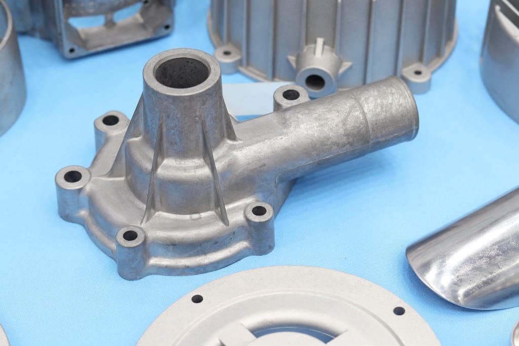
Common Applications of Gravity Die Casting

The following are some notable applications of GDC across various industries:
Automobile
This involves suspension components such as steering knuckles, control arms, wishbones, and wheel hubs are core GDC applications.
Aérospatiale et défense
GDC features prominently in the manufacture of Hydraulic manifolds, avionics housings, structural brackets, and actuator bodies. These parts are typically specified in A357-T6 or 2024-series aluminum.
Équipement industriel
Industrial parts like pump housings, compressor bodies, gearbox end shields, and valve bodies benefit from GDC. That’s because, for these parts, pressure tightness and dimensional repeatability matter more than cosmetic finish.
Équipement médical
Instrument housings, imaging system structural frames, and surgical robot arm components require non-ferrous, heat-treatable, and dimensionally stable castings. That makes gravity die casting a logical choice for these parts.
Marine and Oil/Gas
Copper-alloy GDC in LG2 or CuSn bronze delivers seawater corrosion resistance and wear performance that aluminum alternatives simply can’t match.
Gravity Die Casting Cost Analysis
GDC cost is multi-variable and volume-dependent. There is no single “cost per part” without specifying alloy, geometry, volume, heat treatment requirement, and secondary operations. The tables below break it down systematically so you can model your project accurately.
Note: Costs shown are indicative UK/Europe market rates. Contact Yijin Solution for current pricing applicable to your project.
GDC Cost Element Breakdown
Gravity die casting unit cost has two distinct components: non-recurring tooling investment and recurring per-part cost, which is paid every cycle. Understanding both, and how they interact with volume, is what separates accurate cost modeling from guesswork.
| Cost Element | Gamme typique | Key Cost Driver | Notes |
|---|---|---|---|
| Outillage | $8,000–$40,000 | Complexity, cores and slides, cavity count | One-time capital cost amortized across production volume. Multi-cavity tools increase upfront cost but reduce unit cost at volume. |
| Sand Cores | $1–$10 per core | Core complexity and quantity per casting | Required where die cannot form internal geometry. Specify minimum core count at DFM stage. |
| Die Maintenance and Repair | $500–$5,000/year | Die material, shot count, alloy abrasiveness | GDC dies last 50,000–150,000 shots — longer than HPDC due to lower thermal shock. Budget for planned maintenance intervals. |
| Alloy/Material | $1.50–$6.00/kg | Alloy specification, LME price, returns rate | Aluminum alloys: ~£1.80–£2.50/kg. Returns recycled back — high-yield design reduces material cost. |
| Travail | $5–$25 per part | Cycle time, pouring method | Automating the pour and using trim dies significantly reduces labor content at volume. |
| Traitement thermique | $0.50–$3.00/kg | Treatment specification for T4 vs T6, batch size, furnace utilization | T6 treatment is more expensive than T4. Large batch sizes improve cost per part. |
| Usinage CNC | Part-specific | Number of CTF features, tolerances, setups required | Budget CNC operations at DFM stage — tight-tolerance features on as-cast GDC add significant unit cost if not planned early. |
| Traitement de surface | $0.50–$4.00/part | Process type, especially anodize vs powder coat vs chromate, part size, masking complexity | Specify masking requirements on drawing to avoid cost surprises. |
| Inspection and NDT | $1–$15/part | Visual vs CMM vs X-ray inspection levels, first article vs production | X-ray NDT adds significant cost per part — specify only where structurally justified. |
How Volume Affects Gravity Die Casting Unit Cost
Tooling amortisation is the dominant cost factor at low-to-medium volumes. The crossover from sand casting to GDC economics typically occurs at 500–1,000 parts/year for simple parts. Below that threshold, sand casting’s lower tooling commitment is usually the better financial decision.
| Annual Volume | Tooling Cost/Part (amortized) | Estimated Unit Cost (Al, simple part) | Process Recommendation |
|---|---|---|---|
| < 500 | > $50 | $60–$150+ | Sand casting or investment casting likely more cost-effective unless tight tolerances or heat treatment are mandatory |
| 500–2,000 | $15–$50 | $25–$80 | GDC becomes viable — tooling investment starts to amortise. Ideal for structural prototypes moving to low production. |
| 2,000–10,000 | $5–$15 | $12–$35 | GDC sweet spot. Full tooling amortisation, repeatable quality, and heat-treat capability deliver strong value. |
| 10,000–50,000 | $1–$5 | $6–$20 | GDC highly cost-effective at this volume. Consider multi-cavity tooling to reduce cycle cost. |
| > 50,000 | < $1 | $3–$10 | Evaluate HPDC if wall thickness and geometry permit — faster cycle time reduces unit cost further at high volume. |
Design for Gravity Die Casting — Key DFM Rules
The decisions made at DFM stage determine the majority of your final part cost and quality outcome. The table below translates each design parameter into its cost or quality consequence, so you understand not just what the rule is, but what goes wrong when it’s ignored.
| DFM Parameter | Guideline (aluminum GDC) | Pourquoi c'est important |
|---|---|---|
| Minimum Wall Thickness | 3.0–4.0 mm | Thinner walls increase misrun risk; abrupt thickness transitions cause shrink porosity |
| Angles d'ébauche | 1–3° on all surfaces parallel to draw direction | Required on all vertical faces to allow clean ejection without tearing |
| Fillet Radii | Minimum R2 mm on all internal corners | Sharp corners concentrate thermal stress, crack the die, and initiate shrink porosity |
| Sous-coupes | Minimize — each undercut requires a core or slide | Every undercut adds tooling cost, cycle time, and a potential leak path |
| Cores with respect to internal geometry | Prefer die-formed over sand cores where geometry allows | Sand cores add per-cycle cost and dimensional variation |
| Riser/Feeder Placement | Position risers above the heaviest sections; maintain directional solidification | Poor riser placement is the primary cause of shrink porosity in GDC |
| Ligne de séparation | Agree cosmetic and functional implications before steel is cut | Flash at the parting line is unavoidable — specify acceptable flash height on the drawing |
| CTF Feature Allowance | Leave +0.3–0.8 mm stock on tight-tolerance features for CNC | Do not attempt to hold <±0.15 mm in the as-cast condition |
Au Solution Yijin, our DFM review covers core count, riser placement strategy, parting line implications, and CTF feature allowance before any tooling commitment is made. Bringing us into the design review before the drawing is released eliminates the most expensive late-stage changes.
Gravity Die Casting Quality Standards and Inspection
Quality specification for GDC is a buyer responsibility as much as a foundry responsibility. Undefined acceptance criteria are the most common cause of first-article disputes. Agree the inspection plan and acceptance levels before production starts, not after.
Contrôle dimensionnel
This follows First Article Inspection per AS9102 for aerospace or customer-specific PPAP for automotive applications. Production inspection covers a statistical sample against drawing callouts using CMM or coordinate gauging.
Porosity Specification
Porosity specification has its existence entrenched in ASTM E505 radiographic reference standards, or equivalent OEM-specific reference radiographs. Agree on the acceptance level before production starts. Leaving porosity limits undefined at quoting stage is a common source of late-stage rejection disputes.
Mechanical Property Verification
This uses separately cast test bars per ASTM B108 or BS 1490 to verify UTS, 0.2% proof stress, and elongation for heat-treated GDC. Cutting test bars from production castings is generally not appropriate unless the design specifically provides for it.
Why Partner with Yijin Solution for Gravity Die Casting?
Solution Yijin is a Shenzhen-based precision manufacturing company certified to AS9100D, IATF 16949 and ISO 13485. These are high-level aerospace, medical devices and automotive certifications respectively. We’ve been manufacturing structural castings and precision components since 2003, and our GDC program is built around engineering-first process control — not just production throughput.
We operate standard gravity, tilt-pour, and GDC-with-sand-core processes across aluminum, zinc, magnesium, and copper alloys, covering the full GDC application range without program handoff between suppliers. We perform Usinage CNC, surface treatment like anodizing, powder coating and chromate conversion; pressure testing, and CMM inspection using Zeiss instruments.
Questions fréquemment posées
What is Gravity Die Casting Used For?
Gravity die casting works best when producing structural, non-ferrous metal parts. In such processes, low porosity and heat treatability is a major requirement, primarily in aluminum, copper, and magnesium alloys. Common applications include automotive suspension and engine components, hydraulic manifolds, aerospace structural brackets, and industrial pump housings.
How Much Does Gravity Die Casting Tooling Cost?
GDC tooling typically ranges from $8,000–$40,000, depending on part complexity, number of cores and slides, cavity count, and alloy. Simple single-cavity aluminum tools start at approximately $8,000–$15,000; complex multi-cavity tools with multiple slides and sand core systems can reach $30,000–$40,000 or more.
What is the Difference Between Gravity Die Casting and High-Pressure Die Casting?
The fundamental difference is the fill mechanism. Gravity die casting fills the die under gravity head pressure alone; HPDC injects molten metal at 10–175 MPa. This means GDC produces denser, lower-porosity castings that create full structural tempers when heat treated. On the other hand, HPDC castings don’t respond favorably to heat treatment due to subsurface porosity.
Can Gravity Die Casting Parts Be Heat Treated?
Yes.
Heat treatability is one of GDC’s primary advantages over HPDC. The low porosity achieved by gravity fill means solution treatment and aging, as is the case of T6 temper. When GDC produces A356-T6, the UTS value typically goes above 250 MPa and elongation above 5%.
What is the Minimum Order Quantity for Gravity Die Casting?
There’s no fixed minimum order quantity, but GDC becomes economically competitive from approximately 500–1,000 parts/year for simple parts, where the tooling investment amortises to an acceptable per-part cost.
What Tolerances Can Be Achieved in Gravity Die Casting?
As-cast dimensional tolerances for aluminum GDC typically range from ±0.3–0.8 mm depending on part size and feature location, per ISO 8062 CT7–CT9. Tight-tolerance features such as bores, mating faces, and threads are left with CNC machining allowance of 0.3–0.8 mm stock and finished post-cast to achieve ±0.05–0.1 mm.
How long does Gravity Die Casting Tooling Take to Manufacture?
GDC tooling lead time typically ranges from 8–14 weeks, depending on die complexity, number of cores and slides, and current capacity.
Retour en haut de la page : Gravity Die Casting: Complete Process Guide & Cost Analysis