info@yijinsolution.com
 (+86) 188-2253-7569
Accuracy in sheet metal fabrication is very important, but achieving tight tolerances can be a really difficult task. Inconsistent outcomes can result in project delays and low-quality products. Many manufacturers face such issues where parts don’t align properly due to poor tolerance management.
This blogpost is a complete guide and covers everything you need to know on sheet metal fabrication tolerances, from basic to advanced practices in manufacturing.
What are Sheet Metal Tolerances?
The acceptable difference from specified dimensions in fabricated parts is known as sheet metal tolerances. It is the permissible variation between actual and intended measurements that is important for proper fit and function.
The acceptable range of deviation from measurements or particular dimensions for a manufactured component or part is called Manufacturing tolerance range. For sheet metal manufacturing, tolerances typically range from ±0.005″ to ±0.060”.
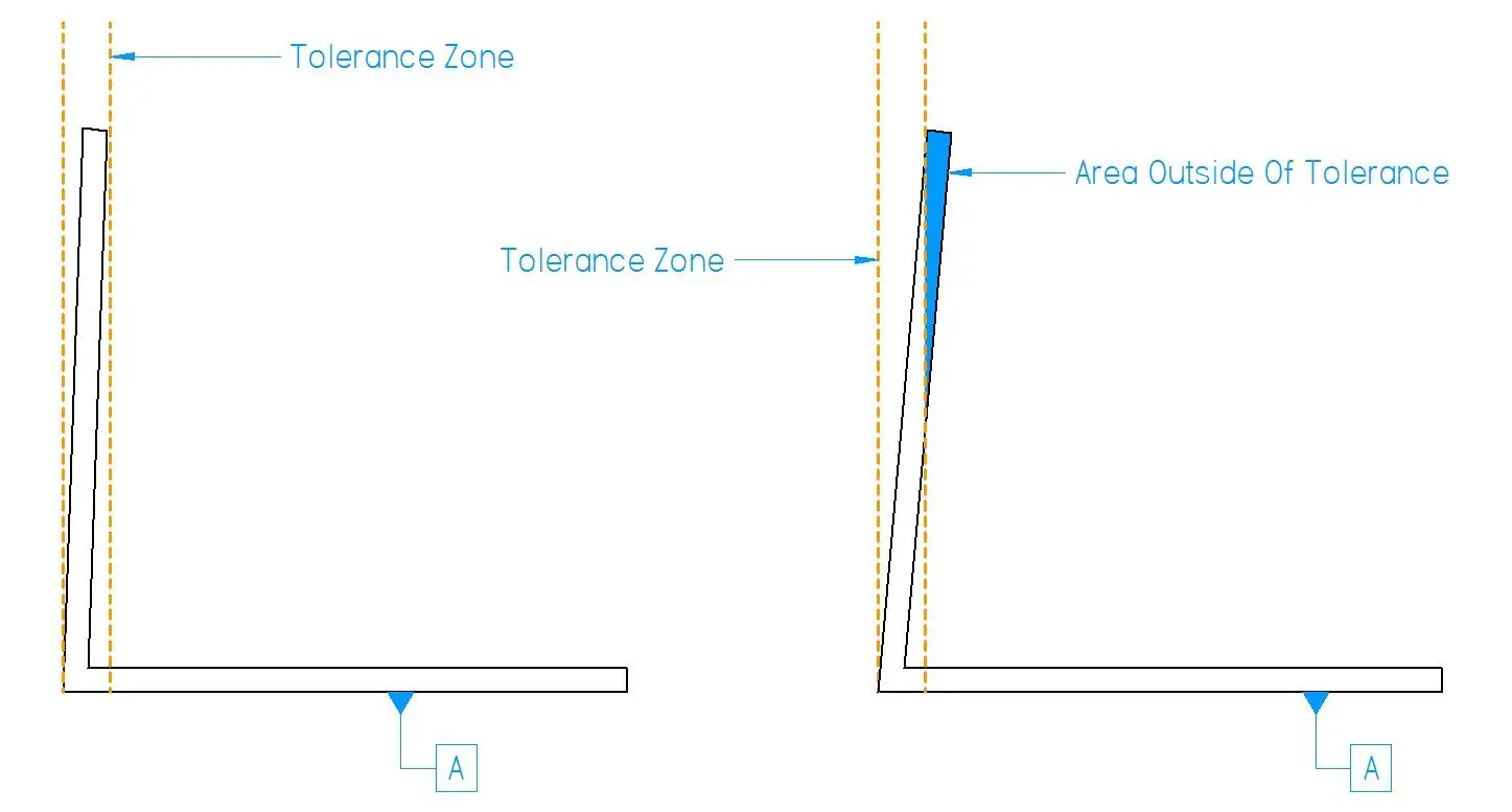
The total permissible variation (upper and lower) in a dimension is known as tolerance zone. Tighter tolerances yield more precise parts but increase production costs. while looser tolerances are economical but may cause alignment issues. This tolerance concept is very important in sheet metal fabrication manufacturing. It makes sure that the parts you get are high quality parts that fit together perfectly.
What Factors Affect Sheet Metal Parts Tolerance?
In this section, we will discuss the different factors that determine sheet metal fabrication tolerances during manufacturing processes. Learning about these factors is important to achieve accurate and consistent results.
Material and Thickness
Different metals have specific properties that determine tolerances. Thicker materials typically allow for looser tolerances, while thinner sheets require tighter control. For example, stainless steel permits stricter tolerances compared to mild steel. If you’re looking for high-precision custom sheet metal fabrication services, selecting the right material and partner is key to achieving desired results.
Cutting and Forming Process
Each fabrication technique has inherent tolerance limits. Laser cutting usually acquires tighter tolerances (±0.005”) than plasma cutting (±0.020”). Shaping processes like bending add more variables that determine the final part dimensions.
Tool and Die Quality
Precision-ground dies and well-maintained tools usually produce parts with tighter tolerances. Low-quality or worn tools can cause inconsistent results. High-end carbide dies can keep tolerances up to 5 times longer compared to standard steel.
Machine Capabilities and Calibration
Advanced CNC machines give outstanding accuracy, with some acquiring tolerances up to ±0.001″. Regular calibration is important even a 0.1° press brake misalignment can cause deviation in bent parts.
Fabrication Company Capabilities
Experienced manufacturers with cutting-edge technology and skilled workers can reach tighter tolerances consistently. ISO 9001 certified companies usually keep tolerances within ±0.005” for important dimensions.
Design Complexity and Geometry
Intricate designs with multiple bends, cuts or features are difficult to fabricate within tight tolerances. Simple, symmetrical parts typically permit tighter tolerances (±0.010”) than complex geometries (±0.030”).
Material Selection
Choosing the right material is important to acquire the desired tolerances in sheet metal fabrication. Each material type has particular properties that determine the manufacturing accuracy and part performance.
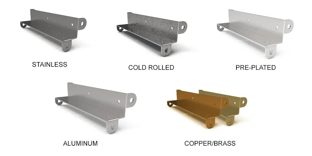
Material Types
For tighter tolerances, materials with high dimensional stability and low thermal expansion are preferred. Both stainless and tool steel are outstanding choices. They have a high elastic modulus (200 GPa) and low thermal expansion coefficient (10-12 × 10^-6/°C). These characteristics resist deformation under stress and temperature changes while keeping dimensions accurate.
For looser tolerances, more malleable materials like aluminum or mild steel are better. Aluminum has a lower elastic modulus (70 GPa) and higher thermal expansion (23 × 10^-6/°C) which makes it easier to shape. Mild steel has a moderate elastic modulus (200 GPa) and thermal expansion (12 × 10^-6/°C) which gives a balance between strength and formability. These materials are more forgiving and less prone to springback in less important applications.
Material Tolerance Properties
Different metals have different tolerance capabilities. Stainless steel typically needs tighter tolerances (±0.005′′) than aluminum (±0.010′′) due to its lower malleability and higher strength. Copper alloys usually fall between these ranges.
This table shows the different values for materials like tolerance range, elastic modulus and thermal expansion coefficient:
| Material | Tolerance Sensitivity | Typical Tolerance Range | Elastic Modulus (GPa) | Thermal Expansion Coefficient (10^-6/°C) |
| Stainless Steel (304) | High | ±0.005″ to ±0.015″ | 200 | 17.3 |
| Tool Steel (D2) | High | ±0.002″ to ±0.010″ | 210 | 10.4 |
| Aluminum (6061-T6) | Moderate | ±0.010″ to ±0.030″ | 70 | 23.6 |
| Mild Steel (1018) | Low | ±0.015″ to ±0.045″ | 205 | 12 |
| Copper (C11000) | Moderate | ±0.008″ to ±0.020″ | 117 | 16.8 |
| Titanium (Grade 5) | High | ±0.005″ to ±0.015″ | 114 | 8.6 |
General Tolerances for Sheet Metal Fabrication
Knowing general tolerances is important for good sheet metal fabrication. They guarantee quality and consistency in manufacturing while balancing cost-effectiveness and accuracy.
The following table outlines typical tolerances for common sheet metal fabrication processes.
| Process | Type | Tolerance Value |
| Laser Cutting | Linear dimensions | ±0.1mm for parts up to 1000mm |
| Hole diameter \< 5mm | ±0.05mm | |
| Hole diameter > 5mm | ±0.1mm | |
| Punching | Linear dimensions | ±0.2mm for parts up to 1000mm |
| Hole diameter | ±0.1mm | |
| Bending | Angular tolerance | ±0.5° |
| Linear dimensions | ±0.3mm for bends up to 1000mm | |
| Stamping | Linear dimensions | ±0.2mm for parts up to 100mm |
| ±0.3mm for parts 100-500mm | ||
| Welding | Linear dimensions | ±0.5mm for weld lengths up to 100mm |
| ±1.0mm for weld lengths 100-500mm | ||
| Forming | Linear dimensions | ±0.5mm for formed features up to 100mm |
| ±0.8mm for formed features 100-500mm |
Sheet Metal Processes & Their Tolerances
Different sheet metal fabrication methods have different tolerance abilities. Learning these differences is important for choosing the appropriate process for your project needs.
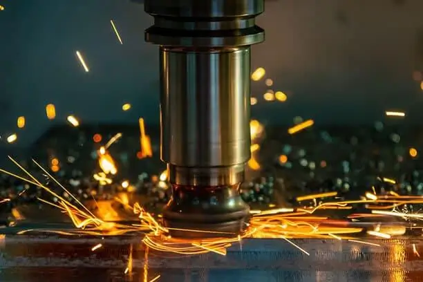
Laser Cutting
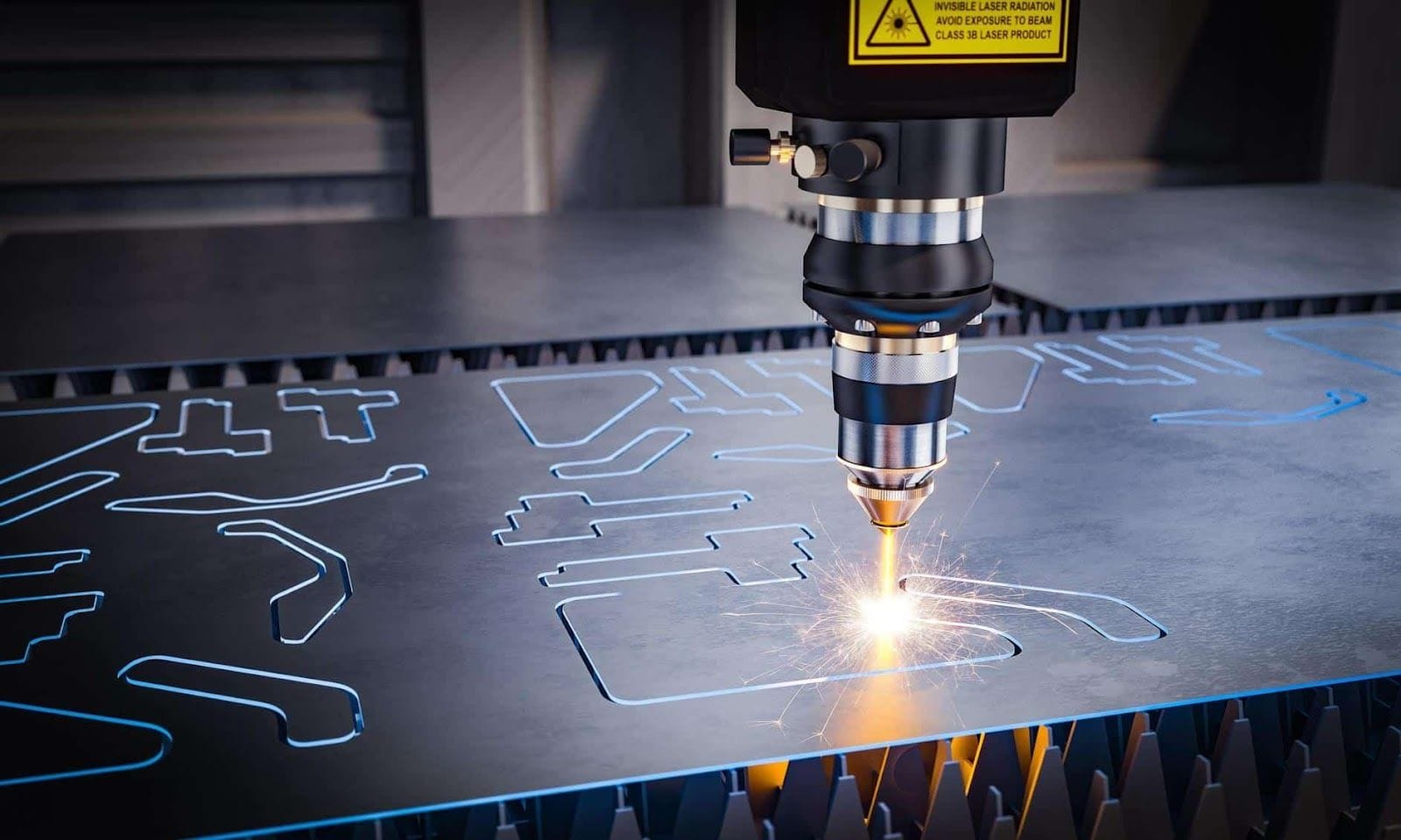
It is an accurate thermal method that uses a focused beam of light to melt, burn or vaporize material. The CNC-controlled laser follows a programmed path and makes intricate shapes with minimal material distortion. This process is best for high volume production and complex geometries.
Laser cutting usually acquires tolerances of ±0.5mm for parts up to 1000mm. For smaller parts (under 100mm), it can be as tight as ±0.05mm.
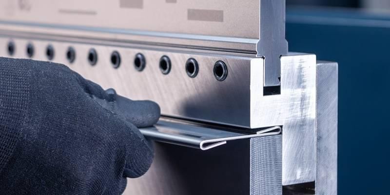
Sheet Metal Bending
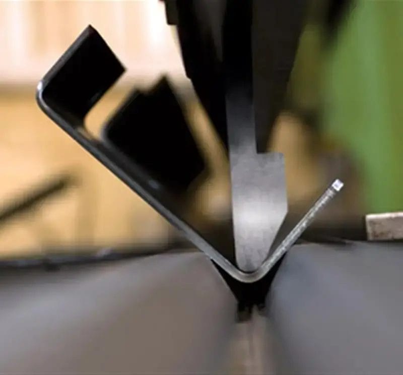
Sheet metal bending involves forming metal around a straight axis to create V, U, or channel shapes. Using precision-ground dies and punches allows for accurate bends. Manufacturers providing sheet metal bending services often ensure tolerances of ±0.5° for angular dimensions and ±0.4mm to ±0.8mm for linear dimensions.
Sheet Metal Welding
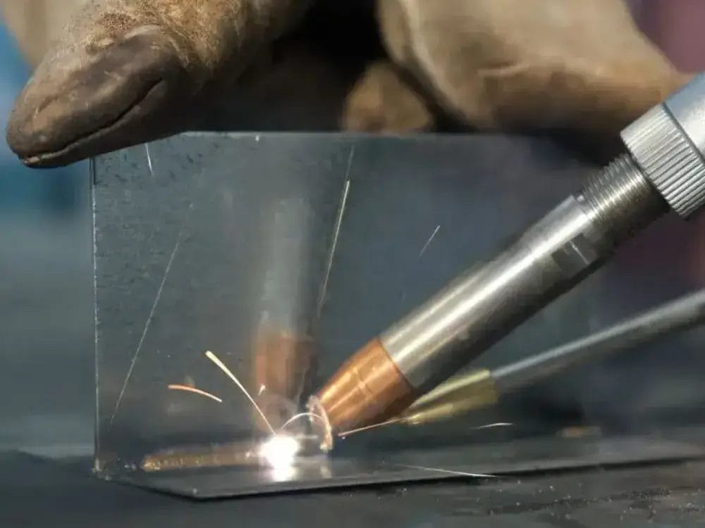
It is a joining process in which two or more metal pieces fuse together using heat, pressure or both. Common methods like MIG, TIG and spot welding are usually used. The process comprises preparing edges, aligning parts, using heat to melt the metal, and allowing it to cool and solidify.
Welding tolerances usually range from ±0.5mm to ±2mm for linear dimensions. Angular dimension values are usually within ±2°.
Sheet Metal Stamping
It is a high-volume manufacturing process that uses dies to transform flat metal sheets into particular shapes. The process starts with inserting the sheet into a stamping press where a tool and die surface apply pressure to form, cut or punch the metal into the desired form.
Stamping tolerances typically range from ±0.1mm to ±0.5mm for most dimensions. Even tighter tolerances of ±0.05mm can be acquired for important features.
Sheet Metal Design Considerations
Good design is important for reaching better tolerances in sheet metal fabrication. Different features and techniques can really determine the manufacturability and final quality of the product.
Bend and Relief Radius
Bend and relief radius are important design elements in sheet metal fabrication. They greatly affect part strength, manufacturability and tolerance control. The bend radius refers to the inside curvature of a bent sheet metal part. On the other hand, Relief radius is a small cutout at the bend intersection to avoid material tearing.
Important bend radius guidelines:
- Minimum bend radius: Use 1-1.5 times the material thickness for most metals.
- Consistency: Keep uniform bending radii of the part in the overall process when possible.
- Material consideration: Adjust radius for material properties (e.g., larger for brittle materials).
Relief radius considerations:
- Size: Mostly 1.5-2 times of the material thickness.
- Placement: Apply at intersecting bends to decrease stress concentration.
- Shape: Use circular or teardrop shapes for better stress distribution.
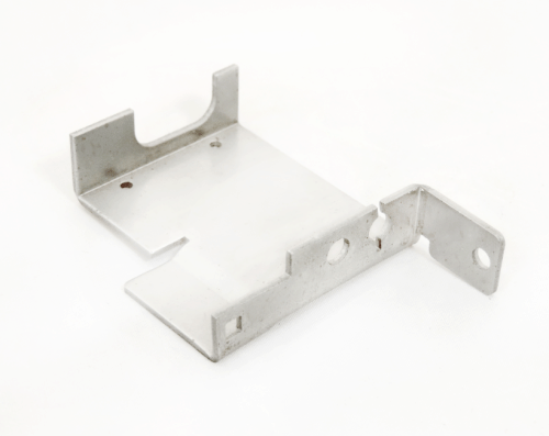
Offset Bends
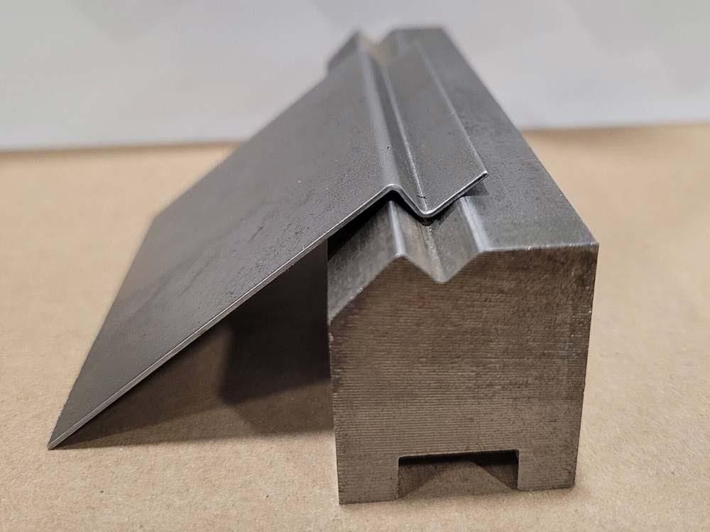
Offset bends are parallel bends going in opposite directions which makes a step or jog in the sheet metal part. They are important for creating complex shapes and increasing part strength. These bends spread stress more evenly over the material which decreases the risk of fatigue failure. This design characteristic increases the structural integrity while allowing for compact, space-efficient parts in assemblies.
Important design considerations for offset bends are:
- Parallel planes – Keep parallel planes at least two times the sheet thickness apart to avoid weakening structure.
- Lazy offsets – For small offsets, expect angles less than 90 degrees on both bends. This helps fabricators reach odd heights when required.
Curls
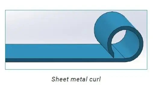
Curls are an important sheet metal design characteristic that increases part strength and safety. They involve rolling the edge of a sheet metal part into a circular profile, typically with an inside radius 1.5 to 2 times of the material thickness.
When designing curls, consider these guidelines like:
- Minimum radius – The outside radius of a curl should not be smaller than 2 times the material thickness. This guarantees enough material flow and prevents fracturing.
- Hole placement – Any holes near curls should be at least the curl radius and the material thickness away from the curl characteristic. This prevents distortion of holes during curling.
Industry Standards for Sheet Metal Tolerances
Different international guidelines standards are set for sheet metal tolerances. These guidelines and standards guarantee quality and consistency across different manufacturers and industries.
ISO 2768
ISO 2768 is an important standard for general tolerances in sheet metal fabrication. It specifies tolerance classes for linear dimensions, angular dimensions (ISO 2768-1) and geometrical tolerances (ISO 2768-2). The standard has four tolerance classes: fine (f), medium (m), coarse (c), and very coarse (v).
ISO 2768 simplifies drawings by removing the need to list tolerances for each dimension. It is globally available in a common language for manufacturers and designers. This guarantees part interchangeability and quality control.
ASME Y14.5
ASME Y14.5 is a thorough standard for dimensioning and tolerancing in engineering drawings. It sets uniform practices for stating and interpreting tolerancing related requirements. The standard characterizes geometric dimensioning and tolerancing (GD&T) symbols, concepts and rules. It comprises 14 geometric characteristics and 5 tolerance zones.
ASME Y14.5 is broadly used in automotive aerospace and manufacturing enterprises. It guarantees clear communication between design and production teams which results in fewer errors and improves product quality and interchangeability.
Conclusion
Learning sheet metal fabrication tolerances is important for making outstanding parts. Important things manufacturers should consider like material properties, choosing appropriate processes, considering design factors and following industry standards. Close control of tolerances guarantees part functionality, interchangeability and product quality.
Yijin Hardware a main sheet metal manufacturer provides expert guidance and accurate fabricating services. For tailored solutions and to examine your particular tolerance requirements contact Yijin Hardware’s engineering team today. Our specialists will help you optimize your structures and designs for manufacturability and cost effectiveness.