The hole is an important surface on the box, bracket, sleeve, ring, and disc parts, and it is also a surface often encountered in machining.
In the case of the same processing accuracy and surface roughness requirements, processing holes is more difficult than processing the outer surface, the productivity is low, and the cost is high.
Compared with the surface processing of the outer circle, the conditions of hole processing are much worse, and it is more difficult to machine the hole than the outer circle.
This is because:
1)The size of the tool used for hole processing is limited by the size of the hole to be processed, and the rigidity is poor, which is prone to bending deformation and vibration.
2)When machining holes with fixed-size cutting tools, the machining size of holes often depends directly on the corresponding size of cutting tools.
The manufacturing error and wear of cutting tools will directly affect the machining accuracy of holes.
When machining holes, the cutting area is inside the workpiece, chip removal, and heat dissipation conditions are poor, and processing accuracy and surface quality are not easy to control.
Common hole processing methods include drilling, reaming, boring, broaching, honing holes, grinding holes, and hole finishing.
Below I will introduce several hole processing techniques and the differences between them in detail to solve the hole processing problems.
What Is Drilling?
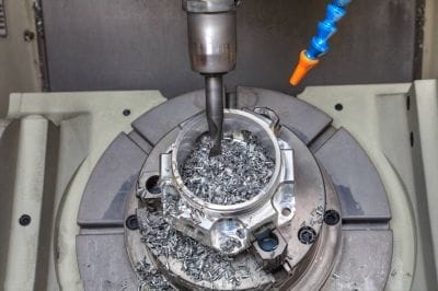
Drilling is the first process of machining holes in solid materials, and the diameter of the holes machined by drilling is generally less than 80mm.
There are two ways of drilling: One is bit rotation; and The other is workpiece rotation.
The errors produced by the above two drilling methods are not the same.
In the drilling method with the drill bit rotating, when the drill bit is deflected due to the asymmetry of the cutting edge and insufficient rigidity of the drill bit, the centerline of the processed hole will be deviated or deviated. Not straight, but the aperture is unchanged;
On the contrary, in the drilling mode of workpiece rotation, the bit deflection will cause the hole diameter to change, but the hole centerline is still straight.
Commonly used drilling tools with a Twist drill, Center drills, Deep hole drills, etc. The most commonly used is the twist drill, its diameter specification is ψ0.1~ψ0.8mm.
Due to the limitations of the structure, the bending stiffness and torsional stiffness of the drill bit are low, coupled with the bad centrality, the precision of drilling is low, generally can only reach IT13 ~ IT11;
The surface roughness is also large, Ra is generally 50-12.5 μm, But the metal cutting rate of drilling is large and the cutting efficiency is high.
Drilling is mainly used to process holes with low-quality requirements, such as bolt holes, threaded bottom holes, and oil holes.
For holes that require high machining accuracy and surface quality, they should be achieved by broaching, reaming, boring, or grinding in the subsequent processing.
Drilling Process
- Marking out: Before drilling, we should be familiar with the drawing requirements. According to the location and size requirements of the drilling, use a height ruler to draw the cross centerline of the hole position. The centerline is clear and accurate, and the thinner the better. After the line is drawn use vernier calipers or steel rulers for inspection.
- To draw a test square or circle: After the line is drawn and passed the inspection, an inspection grid or inspection circle with the centerline of the hole as the symmetric center should be drawn as the inspection line during the trial drilling, so that the drilling position can be checked and corrected when drilling.
- Proofing punch: After marking out the corresponding inspection grid or inspection circle, proofing should be done carefully. Make a small spot first, and observe in different directions of the centerline of the cross to see if the sample punch is at the intersection of the centerline of the cross. Finally, the sample punch is punched to the right to make a circle and to make it larger, so that the drill can be accurately centered.
- Clamping: Wipe clean machine table, fixture surface, workpiece datum, the workpiece clamping, clamping requirements flat, firm, easy to observe, and measure. Attention should be paid to the clamping method of the workpiece to prevent deformation of the workpiece due to clamping.
- Test boring: Before drilling, we must first test drilling, so that the horizontal edge of the drill bit aligns with the center of the hole sample to drill a shallow hole, and then visually test whether the shallow hole position is correct, and constantly correct deviation so that the shallow hole and the test circle coaxial. If the deviation is small, the workpiece can be pushed to the opposite direction of the deviation by force at the same time as drilling, to achieve gradual correction.
- Drilling: Fitter drilling is mainly operated by manual feeding. When the test drilling reaches the accuracy requirement of the drilling position, drilling can be carried out. When feeding manually, the feeding force should not bend the drill bit, so as not to tilt the axis of the hole.
- When we carry out the drilling process, we should choose whether to use the drilling process of the drill bit rotation or the drilling process of the workpiece rotation according to the material and processing requirements of the tool. It is very important to choose which drilling process to process the workpiece.
What Is Broaching
Broaching is to use of a broaching drill to further process a hole that has been drilled, cast, or forged to enlarge the hole diameter and improve the processing quality of the hole.
Broaching can either be used as a pre-machining before finishing holes or as the final machining of holes with low requirements.
The broaching drill is similar to the twist drill, but there are more teeth and no chisel.
Compared with drilling, broaching has the following characteristics:
(1) 3~8 more teeth for reaming drill, with good orientation, and relatively stable cutting.
(2) The broaching tool has no chisel edge, and the cutting conditions are good.
(3) The machining allowance is small, the chip tolerance can be made shallower, the drill core can be made thicker, and the strength and rigidity of the cutter body are better.
The precision of broaching is generally IT11~IT10 and the surface roughness Ra is 12.5~6.3. Broaching is often used to process holes with a diameter of less thanψ100mm.
When drilling a hole with a larger diameter (D ≥30mm), it is often used to pre-drill with a small bit (0.5~0.7 times the diameter of the hole), and then broaching with a reaming drill of the corresponding size, to improve the processing quality and production efficiency of the hole.
In addition, broaching can be processed with cylindrical holes, but also with a variety of special-shaped broaching drills (also known as countersink drills) to process various countersink seat holes and flat faces.
The front-end counter drills often have guide columns and are guided by machined holes.
What Is Reaming?
Reaming is one of the finishing methods of holes, which is widely used in production.
For small holes, compared with internal grinding and fine boring, reaming is a more economical and practical machining method.
1. Reamer
Reamer is generally divided into hand reamer and machine reamer. The hand reamer handle is straight, the working part is longer, and the guiding function is better.
The hand reamer has two kinds of structure: integral and adjustable outer diameter. Machine reamer has two types of structure, one with a handle and the other with a sleeve.
The reamer can process not only circular holes but also taper reamer processing conical holes.
2. Reaming Process and Application
Reaming allowance has a great influence on the quality of reaming, the allowance is too large, the reamer load is large, the cutting edge is quickly blunt, it is not easy to obtain a smooth processing surface, and dimensional tolerance is not easy to ensure;
The margin is too small to remove the tool marks left by the process, and naturally, there is no role in improving the quality of hole processing.
The general coarse hinge allowance is 0.35~0.15mm, and the fine hinge is 01.5~0.05mm.
To avoid a built-up edge, reaming is usually processed at a lower cutting speed (v <8m/min when processing steel and cast iron with a high-speed steel reamer).
The value of the feed is related to the aperture being processed. The larger the aperture is, the greater the feed value is.
When the HSS reamer processes steel and cast iron, the feed is usually taken as 0.3~1mm/r.
Reaming must be cooled, lubricated, and cleaned with appropriate cutting fluid to prevent nodules and remove chips in time. Compared with grinding and boring, reaming productivity is high, easy to ensure the accuracy of the hole;
But reaming can not correct the position error of the axis of the hole, the position accuracy of the hole should be guaranteed by the previous procedure.
Reaming is not suitable for machining stepped holes and blind holes.
The dimensional accuracy of reaming holes is generally IT9 ~ IT7, and the surface roughness Ra is generally 3.2~0.8.
For holes of medium size with high precision requirements (such as IT7 precision holes), the drilling–broaching–reaming process is a typical process commonly used in production.
What Is Boring?
Boring is a machining method that enlarges a prefabricated hole with a cutting tool. Boring can be carried out either on a boring machine or a lathe.
Boring Machining Methods
There are three different machining methods for boring holes.
- The workpiece rotation, the tool for the feed movement on the lathe boring mostly belongs to this kind of boring.
- The process features are: The axis of the hole after machining is consistent with the rotation axis of the workpiece. The roundness of the hole mainly depends on the rotation accuracy of the machine tool spindle.
- The axial geometric shape error of the hole mainly depends on the position accuracy of the tool feed direction relative to the rotation axis of the workpiece.
- This boring method is suitable for machining holes with coaxial requirements on the outer circular surface.
- When the tool rotates, the workpiece makes a feed movement, the boring machine spindle drives the boring tool to rotate, and the worktable drives the workpiece to make a feed movement.
- The tool rotates and performs a feed motion. Using this boring method, the overhang length of the boring bar is changed, and the deformation of the boring bar is also changed.
- The hole near the headstock is large, and the hole is far away from the headstock.
- The hole diameter is small, forming a cone hole. In addition, the overhang length of the boring bar increases, and the bending deformation of the spindle due to its weight also increases, and the axis of the machined hole will be bent accordingly. This type of boring is only suitable for processing short holes.
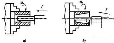
a)Workpiece revolution b)Boring method of tool feed
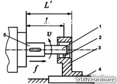
1—Boring bar 2—Boring tool 3—Workpiece 4—Workbench 5—Spindle
Fine Boring Machine
Compared with general boring, diamond boring is characterized by a small amount of back-cutting, small feed, and high cutting speed.
It can obtain high machining accuracy (IT7~IT6) and a very smooth surface (Ra is 0.4~0.05).
Diamond boring was originally processed with diamond boring tools, and now it is generally processed with cemented carbide, CBN, and synthetic diamond tools. Mainly used for processing non-ferrous metal workpieces, also can be used for processing cast iron and steel parts.
The commonly used cutting parameters for diamond boring are: Pre-boring is 0.2~0.6mm, and the final boring is 0.1mm;
The feed rate is 0.01~0.14mm/r; The cutting speed is 100~250m/min when processing cast iron, 150~300m/min when processing steel, and 300~2000m/min when processing non-ferrous metals.
To ensure that the diamond boring can achieve higher processing accuracy and surface quality, the machine tool (diamond boring machine) must have higher geometric accuracy and stiffness.
The machine tool spindle supports commonly used precision angular contact ball bearings or hydrostatic sliding bearings, and high-speed rotating parts must be accurately balanced.
In addition, the movement of the feed mechanism must be very stable to ensure that the worktable can do a steady low-speed feed movement.
The Boring Tool
Boring tools can be divided into single-edged boring tools and double-edged boring tools.
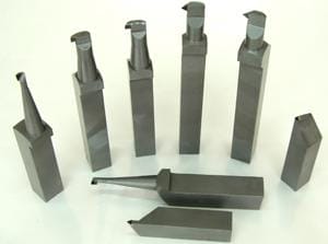
Process Characteristics And Application Scope Of Boring
Compared with the drilling-broaching-reaming process, the aperture size is not limited by the tool size, and the boring has a strong error correction ability.
The deviation of the original hole axis can be corrected through multiple passes, and it can make the boring and positioning surface maintain high position accuracy.
Compared with the outer circle of turning, the boring system has poor rigidity, large deformation, and poor heat dissipation and chip removal conditions, and the thermal deformation of the workpiece and the tool is relatively large.
The processing quality and production efficiency of the boring are not as high as the outer circle of turning. In summary, the processing range of boring is wide, which can process holes of different sizes and different precision levels.
For holes and holes with a larger aperture and higher precision requirements of size and position, boring is almost the only processing method.
The machining accuracy of boring is IT9 ~ IT7, and the surface roughness Ra is small. Boring can be performed on machine tools such as boring machines, lathes, milling machines, etc.
It has the advantages of mobility and flexibility and is widely used in production. In mass production, the boring die is often used to improve the efficiency of the boring.
What Is Honed Bore?
Honing Principle and Honing Head
Honing is a method that uses a honing head with a grinding rod (whetstone) to smooth the hole.
During honing, the workpiece is fixed, and the honing head rotates and moves in a reciprocating straight line driven by the machine tool spindle.
In the honing process, the grinding rod acts on the surface of the workpiece with a certain pressure to remove a very thin layer of material from the surface of the workpiece, and the cutting track is a cross net.
To make the trajectory of the abrasive grains not repeat, the number of revolutions per minute of the honing head’s rotary motion and the number of reciprocating strokes per minute of the honing head should be mutually prime.
The intersection Angle θ of the honing track is related to the reciprocating velocity υa and circumference velocity υc of the honing head.
The size of θ Angle affects the processing quality and efficiency of honing. Generally, θ=40~60° is chosen for rough honing.
To discharge the broken abrasive particles and chips, reduce the cutting temperature, and improve the machining quality, sufficient cutting fluid should be used in honing.
To make the whole wall be processed evenly, the stroke of the sand bar must exceed a certain amount of overtravel at both ends of the hole.
To ensure uniform honing allowance and reduce the influence of machine tool spindle rotation error on machining accuracy, most honing heads and machine tool spindles are connected by floating connections.
The radial expansion and contraction adjustment of the honing head grinding rod has various structures such as manual, pneumatic, and hydraulic.
Process Characteristics And Application Scope of Honing
- Honing can obtain high dimensional accuracy and shape accuracy, and the machining accuracy is IT7~IT6. The roundness and cylindricity errors of the hole can be controlled within a specific range, but honing cannot improve the position accuracy of the processed hole.
- Honing can obtain high surface quality, with surface roughness Ra of 0.2~0.025μm, and the depth of the deformed defect layer of the surface metal is extremely small(2.5~25μm).
- Compared with the grinding speed, the circumferential speed of the honing head is not high (vc=16~60m/min), but due to the large contact area between the sand bar and the workpiece, the reciprocating speed is relatively high (va=8~20m/min), so honing still has higher productivity.
- Honing is widely used in the machining of precision holes in engine cylinder bores and various hydraulic devices in mass production and can process deep holes with a length-to-diameter ratio greater than 10.
- But honing is not suitable for processing the holes on the non-ferrous metal workpiece with large plasticity, nor can it process the holes with keyway, spline holes, etc.
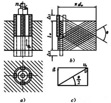
Principle of honing
a) building motion b)Expansion diagram of sand bar grinding track c)Resultant speed
What Is a Draw Hole?
1. Broaching And Broaching Tool
Broaching is a high-productivity finishing method, which is carried out on a broaching machine with a special broach. Broaching machines are divided into two types:
Horizontal broaching machines and vertical broaching machines. Horizontal broaching machines are the most common.
When broaching, the broach only makes a low-speed linear motion (main motion). The number of teeth of the broach working at the same time should not be less than 3, otherwise, the broach work is not smooth, and easy to produce ring ripples on the surface of the workpiece.
To prevent the broach from being broken due to excessive broaching force, when the broach is working, the number of working teeth at the same time should generally not exceed 6 to 8.
There are three different broaching methods for broaching, which are described as follows:
1) Layered Stepping
The characteristic of this broaching method is that the broach cuts the machining allowance of the workpiece layer by layer.
To facilitate chip breaking, the cutter teeth are ground with interlaced chip dividing grooves.
Broaches designed according to the layered broaching method are called ordinary broaches.
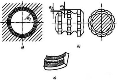
Layered Stepping
a)Draw hole graphics b)Cutting part tooth profile c)Cuttings
2) Skip Stepping
The characteristic of this broaching method is that each layer of metal on the machined surface is cut by a set of cutter teeth (usually composed of 2-3 cutter teeth) that are the same size as the cutter teeth interlaced.
Each tooth removes only part of a layer of metal. The broach designed by block broaching is called rotary broach.
3) Integrated Broaching
In this way, the advantages of layer broaching and block broaching are concentrated.
Block broaching is used for coarse gear cutting, and layer broaching is used for fine gear cutting. In this way, broach length can be shortened, productivity can be improved, and better surface quality can be obtained.
A broach designed by the comprehensive broaching method is called a comprehensive broach.
2. Process Characteristics and Application Scope of Draw Hole
1) A broach is a multi-edged tool, that can complete the roughing, finishing, and smoothing of the hole in sequence in one broaching stroke, with high production efficiency.
2) The precision of broaching mainly depends on the precision of the broach. Under normal conditions, the precision of broaching can reach IT9~IT7, and the surface roughness Ra can reach 6.3~1.6 μm.
3) When broaching, the workpiece is positioned by the machined hole itself (the leading part of the broach is the positioning element of the workpiece), and it is difficult to ensure the mutual position accuracy of the hole and other surfaces when the hole is pulled;
Those inner and outer circular surfaces with coaxial requirements of the rotary parts of the processing are often the first hole, and then the hole as the positioning datum processing of other surfaces.
4) The broach can not only process round holes but also process shaped holes and spline holes.
5) Broach is a fixed-size tool with complex shapes and high prices, which is not suitable for processing large holes.
Broaching is commonly used in a large mass production processing aperture of ф 10~80mm, hole depth not more than 5 times the aperture of small and medium-sized parts through the hole.
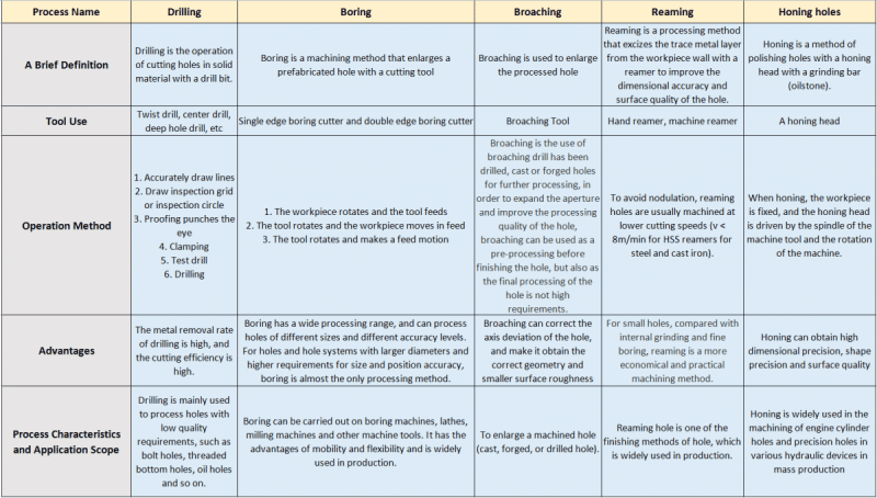
Differences Between Drilling, Boring, Broaching, Reaming, and Honing
Thank you for reading! Any questions, contact our team members freely.

 info@yijinsolution.com
 (+86) 188-2253-7569
