What are CNC lathe codes?
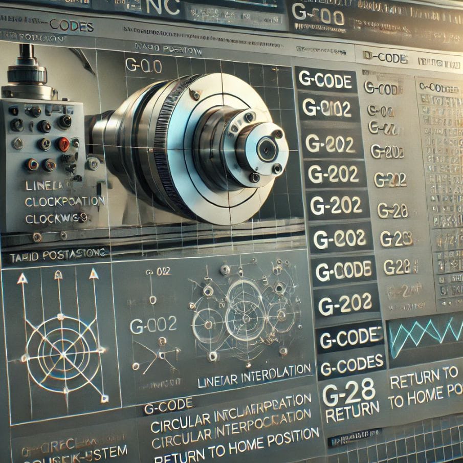
CNC lathe codes consist primarily of G-codes and M-codes, along with address codes and canned cycles. These codes form a programming language that controls the operations of a CNC lathe, including tool movement, spindle control, coolant management, and various machining functions.
The codes can range from simple movement commands to complex parametric programming, allowing for precise control and automation of the machining process.
Common G-codes and M-codes in CNC Lathe Programming
This table covers the most commonly used G-codes and M-codes in CNC lathe programming.
Note that some codes may vary slightly depending on the specific CNC control system being used. Always refer to your machine’s programming manual for the exact implementation of these codes.
| Code | Category | Function | Notes |
| G00 | Motion | Rapid positioning | Moves at maximum speed to specified position |
| G01 | Motion | Linear interpolation | Moves in a straight line at specified feed rate |
| G02 | Motion | Circular interpolation CW | Creates clockwise circular arc |
| G03 | Motion | Circular interpolation CCW | Creates counterclockwise circular arc |
| G20 | Unit | Inch system | Sets programming to inch system |
| G21 | Unit | Metric system | Sets programming to metric system |
| G28 | Motion | Return to home position | Moves to machine zero point |
| G96 | Spindle | Constant surface speed | Maintains constant cutting speed |
| G97 | Spindle | Constant spindle speed | Maintains constant RPM |
| M03 | Miscellaneous | Spindle on clockwise | Starts spindle rotation clockwise |
| M04 | Miscellaneous | Spindle on counterclockwise | Starts spindle rotation counterclockwise |
| M05 | Miscellaneous | Spindle stop | Stops spindle rotation |
| M30 | Miscellaneous | Program end | Ends program and resets |
| G00 | Motion | Rapid positioning | Moves at maximum speed to specified position |
| G01 | Motion | Linear interpolation | Moves in a straight line at specified feed rate |
| G02 | Motion | Circular interpolation CW | Creates clockwise circular arc |
| G03 | Motion | Circular interpolation CCW | Creates counterclockwise circular arc |
| G04 | Dwell | Dwell | Pause program for specified time |
| G20 | Unit | Inch system | Sets programming to inch system |
| G21 | Unit | Metric system | Sets programming to metric system |
| G28 | Motion | Return to home position | Moves to machine zero point |
| G40 | Compensation | Tool nose compensation cancel | Cancels tool nose radius compensation |
| G41 | Compensation | Tool nose compensation left | Applies left tool nose radius compensation |
| G42 | Compensation | Tool nose compensation right | Applies right tool nose radius compensation |
| G50 | Setting | Set coordinate system | Establishes a coordinate system |
| G54 | Coordinate | Work coordinate system 1 | Selects work coordinate system 1 |
| G55 | Coordinate | Work coordinate system 2 | Selects work coordinate system 2 |
| G56 | Coordinate | Work coordinate system 3 | Selects work coordinate system 3 |
| G57 | Coordinate | Work coordinate system 4 | Selects work coordinate system 4 |
| G58 | Coordinate | Work coordinate system 5 | Selects work coordinate system 5 |
| G59 | Coordinate | Work coordinate system 6 | Selects work coordinate system 6 |
| G70 | Cycle | Finishing cycle | Performs finishing cycle |
| G71 | Cycle | Stock removal in turning | Performs rough turning cycle |
| G72 | Cycle | Stock removal in facing | Performs rough facing cycle |
| G73 | Cycle | Pattern repeating | Performs pattern repeating cycle |
| G74 | Cycle | Face grooving | Performs face grooving cycle |
| G75 | Cycle | Outer/Inner diameter grooving | Performs OD/ID grooving cycle |
| G76 | Cycle | Threading cycle | Performs multi-pass threading cycle |
| G90 | Mode | Absolute programming | Sets absolute coordinate programming |
| G91 | Mode | Incremental programming | Sets incremental coordinate programming |
| G94 | Feed | Feed per minute | Sets feed rate in units per minute |
| G95 | Feed | Feed per revolution | Sets feed rate in units per revolution |
| G96 | Spindle | Constant surface speed | Maintains constant cutting speed |
| G97 | Spindle | Constant spindle speed | Maintains constant RPM |
| G98 | Return | Return to initial level | Returns to initial Z-axis level in canned cycles |
| G99 | Return | Return to R level | Returns to R-axis level in canned cycles |
| M00 | Miscellaneous | Program stop | Stops program execution |
| M01 | Miscellaneous | Optional stop | Stops program if optional stop switch is on |
| M03 | Miscellaneous | Spindle on clockwise | Starts spindle rotation clockwise |
| M04 | Miscellaneous | Spindle on counterclockwise | Starts spindle rotation counterclockwise |
| M05 | Miscellaneous | Spindle stop | Stops spindle rotation |
| M06 | Miscellaneous | Tool change | Performs automatic tool change |
| M08 | Miscellaneous | Coolant on | Turns on flood coolant |
| M09 | Miscellaneous | Coolant off | Turns off all coolant |
| M10 | Miscellaneous | Chuck clamp | Clamps the chuck |
| M11 | Miscellaneous | Chuck unclamp | Unclamps the chuck |
| M19 | Miscellaneous | Oriented spindle stop | Stops spindle at a specific orientation |
| M30 | Miscellaneous | Program end | Ends program and resets |
| M41 | Miscellaneous | Gear select 1 | Selects spindle gear range 1 |
| M42 | Miscellaneous | Gear select 2 | Selects spindle gear range 2 |
| M43 | Miscellaneous | Gear select 3 | Selects spindle gear range 3 |
| M44 | Miscellaneous | Gear select 4 | Selects spindle gear range 4 |
| M98 | Miscellaneous | Subprogram call | Calls a subprogram |
| M99 | Miscellaneous | Subprogram end | Ends a subprogram and returns |
Example of a simple CNC lathe program:
O1000 (SIMPLE TURNING PROGRAM)
G21 G40 G95 G97
G28 U0 W0
T0101 (TURNING TOOL)
G50 S2000
G96 S180 M03
G00 X50.0 Z0.1
G01 X-1.6 F0.15
G00 X50.0 Z2.0
G28 U0 W0
M30
This program does the following:
- Sets up the machine (metric, tool comp off, feed per rev, constant RPM)
- Returns to home position
- Selects tool 1
- Sets max spindle speed and turns on constant surface speed
- Moves to starting position
- Performs a facing cut
- Retracts
- Returns home
- Ends the program
While these codes are standardized to some extent, there can be variations between different machine manufacturers and controllers.
Back to Top: CNC Lathe Codes

 info@yijinsolution.com
 (+86) 188-2253-7569


