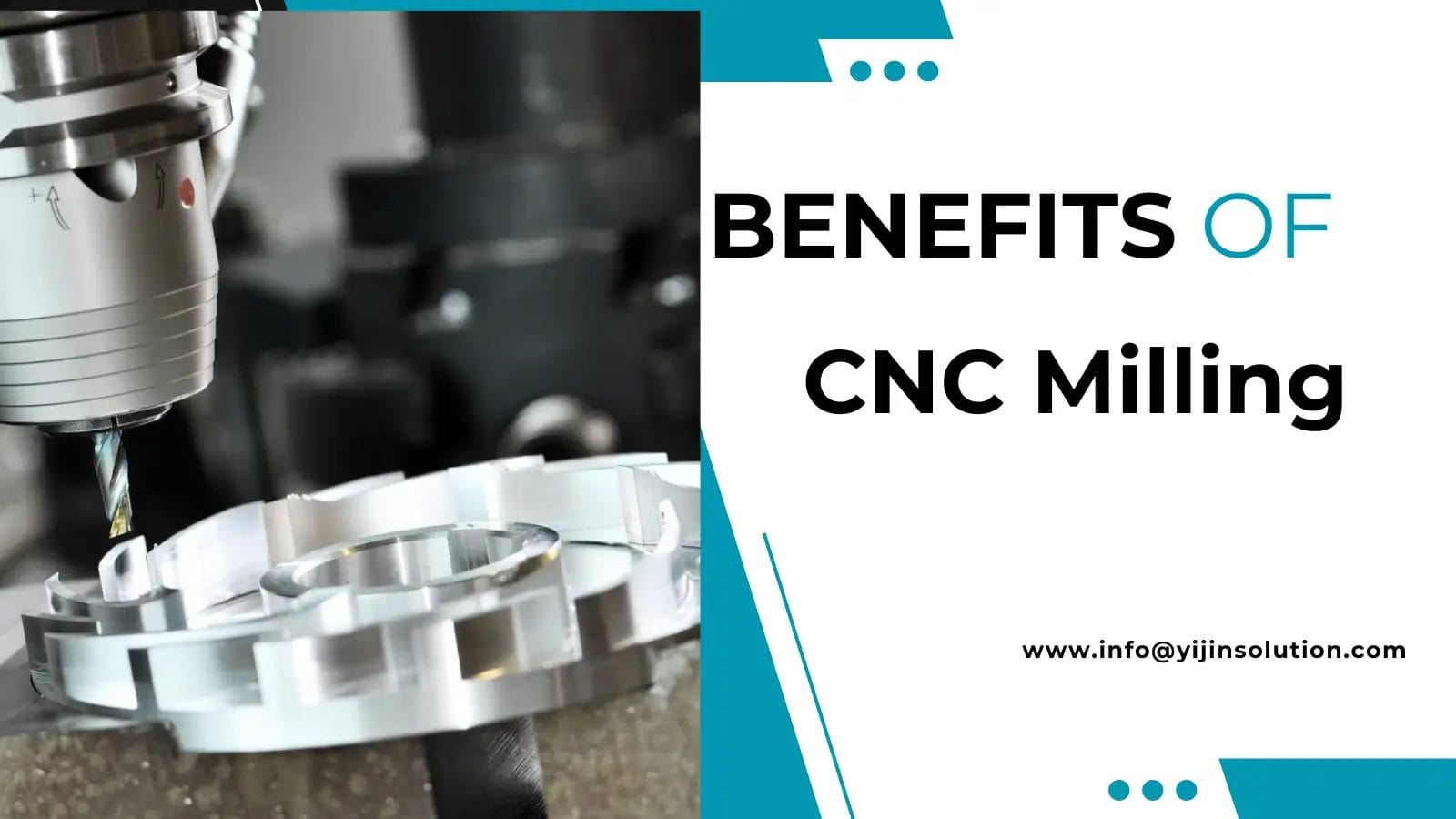
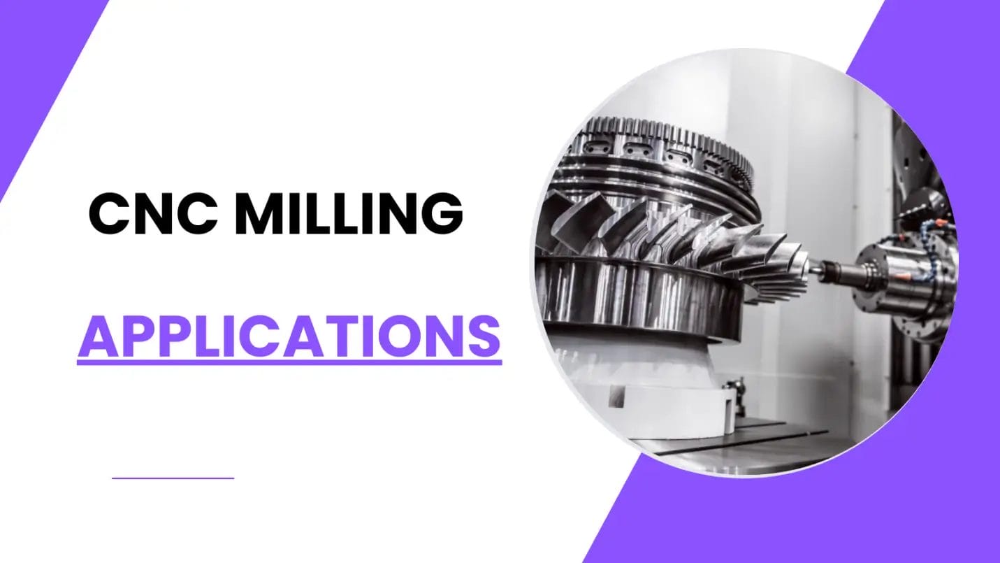
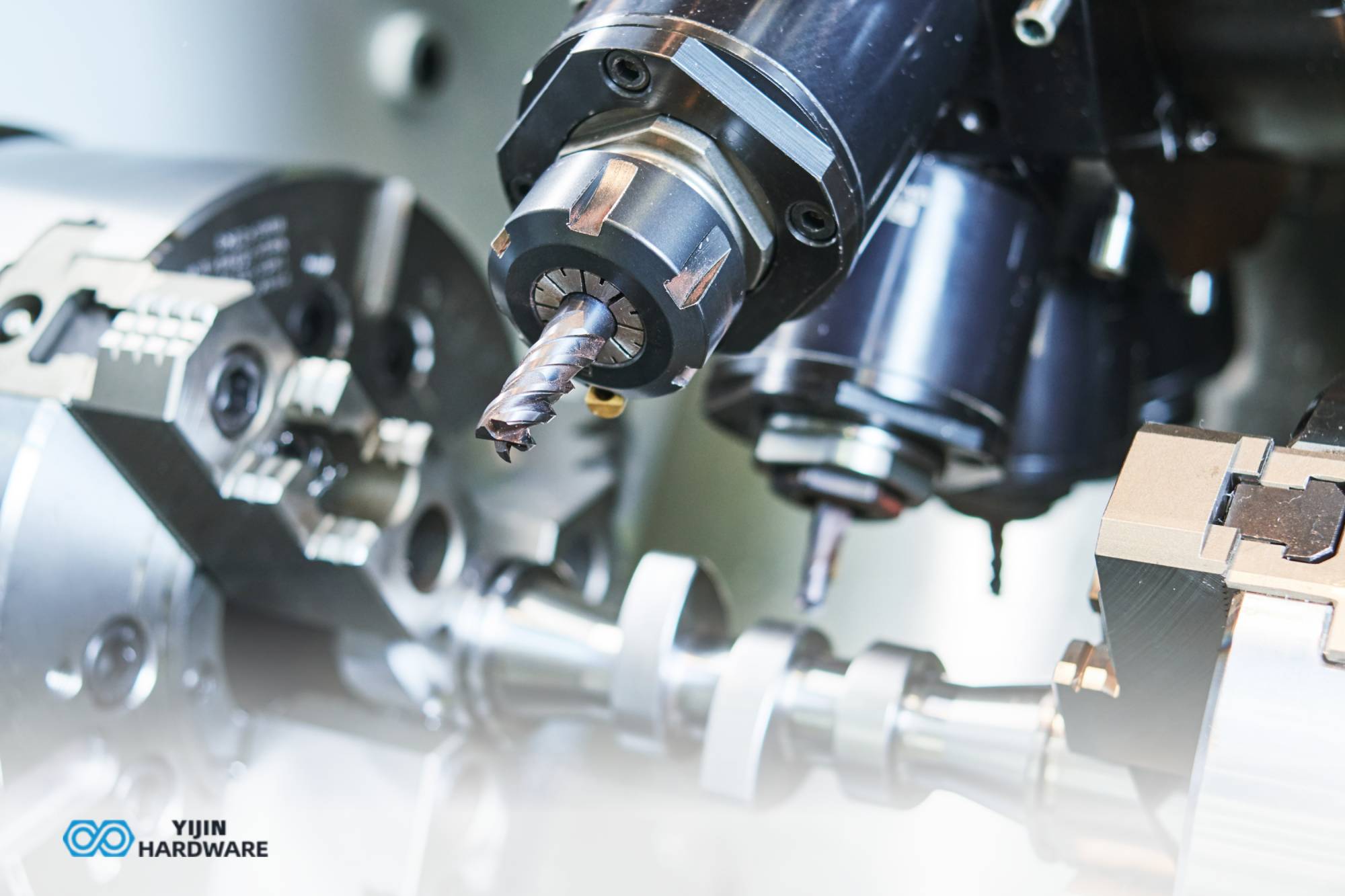
Planes, rockets, vehicles, and boats are all items made using a manufacturing technology called CNC machining. You may be pretty familiar with this technology if you are an engineer. However, this might be a new concept if you are not an engineer. CNC machining is fascinating because it can create countless things and has contributed significantly to the development of modern technologies, from computers to vehicles.With the rise in demand for plastic parts, the mold processing industry is growing rapidly. It is bringing high economic value. CNC milling is divided into types based on the number of axes processed. For instance, 4-axis and 5-axis machines are becoming more popular. Five-axis CNC milling machines can process almost all types of profiles with very high productivity.
What is CNC milling?
CNC machining technology is swiftly adopting new ways to make custom metal and plastic parts. CNC machining companies are incorporating latest materials and technologies. They are manufacturing these parts with greater precision.
“CNC milling machining, which stands for Computer Numerical Control? It is a form of digital manufacturing technology. CNC machining controls precise parts from the digital models.
Learn More:
How Much Does CNC Milling Cost?
Types of Milling Operations

First, there are several types of milling, and one of these methods is called plane cutting. The process of cutting a surface parallel to the table is called plane cutting or face cutting.
Face Cutting
Face cutting is a machining method using a tool called a face milling cutter. Surface milling, also called face milling, is excellent for production efficiency and precision, and in most cases, this method is used for plane cutting. As shown in this figure, the plane is cut by feeding the tool against the tool plane.
End Milling
This is a machining method that uses a tool called an end mill to cut a small area, compared to the face mill we saw earlier.
Side Milling
Next is side milling. This is a processing method that uses a tool called a face milling cutter on a small milling machine to cut a surface. It has excellent cutting efficiency, but the flatness is inferior to that of a face milling cutter. It is suitable for products that do not require precision or for rough cutting. The state shown in the figure is that of side milling. This is a process to cut the side of the workpiece. We call it side cutting or side milling.
In face milling, a horizontal milling machine is attached with a face milling cutter, and the side is cut horizontally. This method is often used for horizontal surfaces.
Stepped Processing
The operator will machine the step on the flat surface. When processing a wide area, a vertical milling machine is suitable for cutting efficiently. For a narrow area, such as a staircase, a horizontal milling machine is suitable for cutting.
An end mill is also used for groove processing. A horizontal milling machine is suitable for cutting a narrow area. The bottom of the groove is wide. For example, a groove where a bolt passes under the groove, like the table surface of a machine tool. To make a groove, first use an end mill to make a groove. Next, a milling tool called a keyway milling cutter is used to finish the groove into the desired shape.
Dovetail Groove Processing
A dovetail groove is a type of trapezoidal groove with a wide bottom. It has a guide surface for the lathe and the feed device. The processing method is to create the groove using an end mill or face milling cutter and then use each milling cutter to finish it into a trapezoid shape.
How to choose type of CNC milling?
1. High-Speed Milling (HSM):
Concept:
HSM employs much higher spindle speeds than conventional milling ranging from 20000 RPM and above and smaller tool diameter of less than 6mm. This combination allows for:
1. Faster Material Removal:
Higher speeds mean you get swift cutting and minimum machining times.
2. Improved Surface Finish:
Moreover, smaller tools bring smaller chip sizes. Ultimately, it shows flawless surface finishing.
3. Reduced Cutting Forces:
Two things impact cutting forces; smaller tool diameter and higher speed.
Applications:
HSM excels in machining:
1. Soft Materials:
Aluminum, plastics, and composites benefit from HSM due to their machinability at high speeds.
2. Thin-Walled Parts:
Reduced cutting forces minimize distortion in delicate workpieces.
3. Mold and Die Making:
HSM’s smooth finishes are ideal for creating mold and die surfaces.
Challenges:
HSM requires specialized considerations:
1. Machine Compatibility:
Machines need high-speed spindles and rigid construction to handle HSM dynamics.
2. Tool Selection:
Specialized HSM tooling with high-performance coatings are crucial.
3. CAM Programming:
Toolpath strategies need to be optimized for HSM’s unique characteristics.
2. Helical Milling:
Concept:
It is different from standard milling. The cutting tool used in helical milling moves in a helical or spiral. Cross milling has a straight path. This offers advantages like:
1. Continuous Chip Removal:
The helical path performs two functions: reducing chip re-cutting and improves surface finish.
2. Reduced Cutting Forces:
Reduced cutting forces minimize tool deflection.
3. Improved Tool Life:
Continuous chip removal and reduced cutting forces extend tool life between changes.
Applications:
Helical milling is beneficial for:
1. Slotting and Pocketing:
The continuous chip removal and reduced forces are ideal for these applications.
2. Three-Dimensional Contours:
Helical toolpaths can create smooth finishes on complex geometries.
3. Hard Materials:
Reduced cutting forces make helical milling suitable for machining challenging materials.
Challenges:
Helical milling requires:
1. Advanced CAM Programming:
Creating optimized helical toolpaths necessitates advanced CAM software capabilities.
2. Machine Compatibility:
Machines with good path control and smooth axis movements are preferred.
3. Trochoidal Milling:
Concept:
This innovative milling technique utilizes a specifically designed toolpath. It resembles a trochoid (a combination of circular and linear motions). Advantages include:
1. Reduced Cutting Forces:
The scalloped toolpath distributes cutting forces more evenly. It minimizes deflection and tool wear.
2. Improved Chip Control:
The trochoidal motion promotes smooth chip evacuation. It reduces chip re-cutting.
3. Extended Tool Life:
Lower cutting forces and improved chip control contribute to longer tool life.
Applications:
Trochoidal milling is well-suited for:
1. High-Volume Production:
The method’s efficiency translates to faster machining times in production settings.
2. Difficult-to-Machining Materials:
Low cutting forces make the process flawless for difficult materials like titanium alloys.
3. Three-Dimensional Features:
Trochoidal toolpaths leads to smooth finishes on complex geometries.
Challenges:
Trochoidal milling requires:
1. Advanced CAM Software:
Generating optimized trochoidal toolpaths necessitates specialized CAM capabilities.
2. Machine Kinematics:
Machines with good dynamic response and smooth axis movements are preferred.
Benefits and Capabilities of CNC Milling

CNC milling has many benefits. It can work on different surface finishing. They can produce high level of accuracy and details. Moreover, these machines are better than old machining methods. With advancement in the manufacturing machining industry, there is a high demand for the qualified CNC turning machinists. Experience in CNC turning machining opens up good paid and stable work. It also has a great future development.
CNC milling machining can also make shapes in the 2D, 3D. The possibilities for technology are practically endless.
Learn More:
Structure and Operation
A CNC milling machine consists of two main parts:
- The control part
- Execution part.
The control part includes program control circuits. Similarly, the execution part is the processing machine. It includes:
- Machine body
- Table
- Motors
- transmission shafts
- Tool holder with multiple tools.
CNC milling machines have two main actions:
- Circular motion for cutting.
- Movement of the machine table along the XYZ axis to shape the machined part.
These movements make CNC milling machines ideal for processing rectangular box-shaped parts. These come with flat surfaces, holes, and 3D profiles used in complex parts and molds. Five-axis milling machines can handle even more complex profiles.
CNC Milling Process
The first step in CNC milling is programming. There are two basic ways to program:
1. G-code:
Traditional form for simple 2D details.
2. CAM software:
Modern method for complex profiles. It carries re-made processing commands to set machine speed, spindle speed, and tool paths.
Common CAM software includes Shimatron and Create. After programming, simulate the program to ensure accuracy, then output a DC program to load into the CNC milling machine.
Setting Up for Milling
To start processing on a CNC milling machine:
- Secure the part using a vise or other tools.
- Set parameters to create the coordinates, establishing the relative position of the workpiece and the tool.
Applications and Materials

CNC milling machines can process flat surfaces, holes, threads, and more. They handle various materials, including plastic, aluminum, copper, steel, and even very hard steels. With practice, CNC milling machines can achieve high productivity.
The most common type of machining on CNC milling machines today is 2D machining for machine parts. However, 3D machining is also increasingly popular. It is famous for processing more complex parts. These parts are used in molds and plastic injection machines.
CNC Machining Tools
Mills, lathe, grinders, and routers are power tools that are electrically operated and computerized. This level of automation makes CNC machining to have minimal human intervention during the production process. Therefore, CNC machining is fairly affordable for prototypes and small series production.
CNC machining is listed under the category of subtractive manufacturing. These parts are produced by removing material from a solid material. They are known as workpiece. This process is fully automated and it entails several steps.
CNC Machining vs. 3D Printing
CNC machining is a type of machining process that is another type than 3D printing in that it is subtractive. In 3D printing materials are built up to make a part, while in CNC machining materials are cut away to make a part. This fundamental difference implies that the two technologies find their way in different areas of use.
Materials Used in CNC Machining
CNC machines can process a wide range of materials. Some of the most popular materials include:
- Aluminum
- Brass
- ABS (Acrylonitrile Butadiene Styrene)
- Nylon
The tolerance in CNC machining can be as low as ±0. 125 mm and in special cases even to ±0. 050 mm or ±0. This level of accuracy ranges from 0.025mm, and this is what makes the CNC machines to produce details as small as a human hair.
Why choose Yijin as your milling partner?
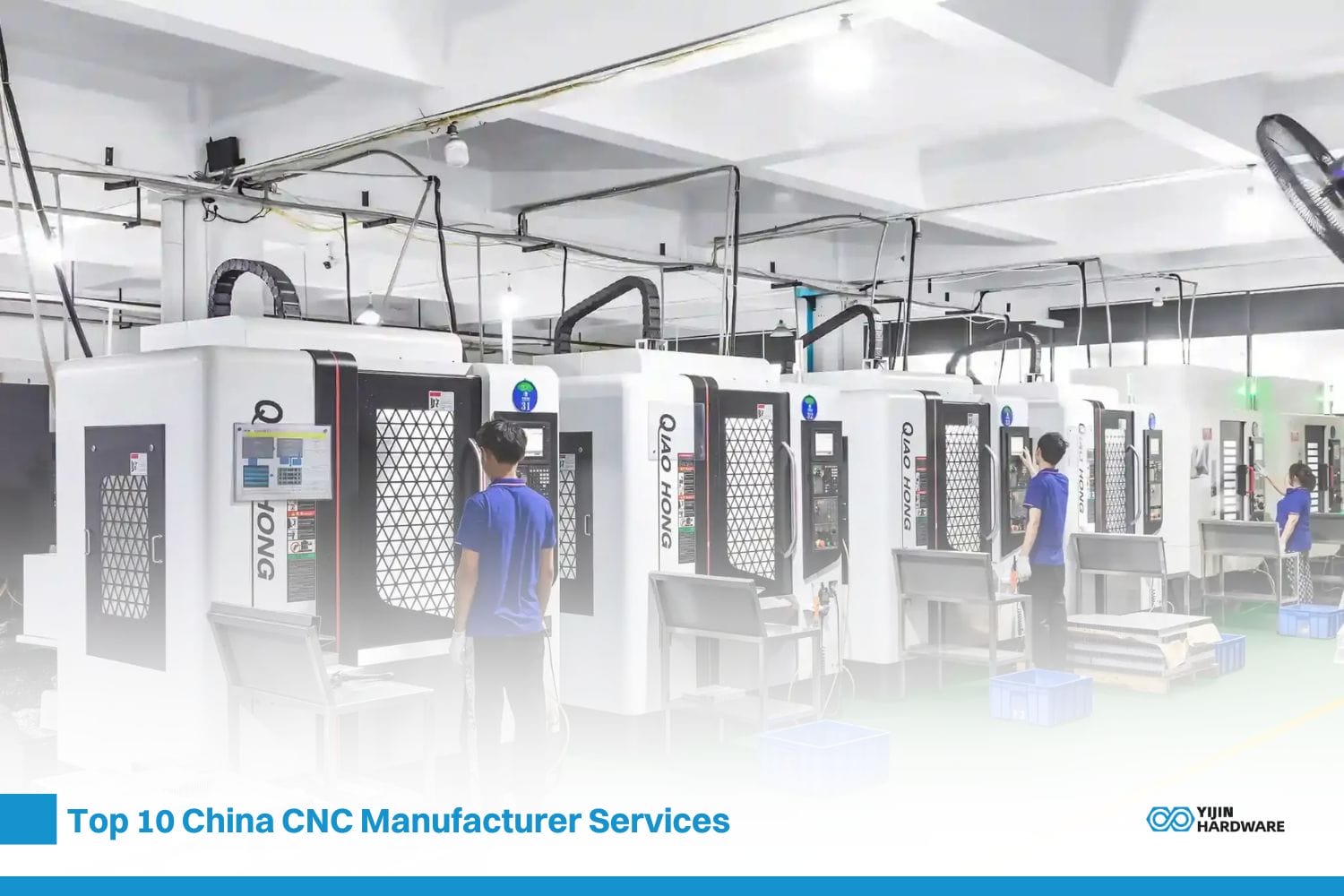
Yijin Hardware is the leading CNC milling company in China. It provides following milling capabilities for rapid prototypes and production parts:
- 3-axis, 4-axis, and 5-axis machining
- Over 50 material choices
- Various surface finishes
- Custom designs
- Tight tolerances down to 0.05mm
Conclusion
CNC machining is the future of modern manufacturing industry. From making complex engine parts to developing prototypes for EV companies, you can see unparalleled demand of custom parts. Therefore, CNC milling technology is paving its way to high precision with tighter tolerance to meet custom designs perfectly.

 info@yijinsolution.com
 (+86) 188-2253-7569


