(+86) 188-2253-7569
Engineering Drawing Components: Key to Mechanical and Technical Success
From angles to lines, from scaling to dimensions – engineering drawings are essential for a successful project in the mechanical and technical fields.
It’s all about accuracy, precision and understanding the tiny details that make up the big picture.
The visual representation of an idea, product, or concept comes in the form of shapes, lines and symbols, so it’s important to have a good grasp of what these components mean in order to be successful.
Importance of Engineering Drawings in Mechanical and Technical Fields:
- Engineering drawings help to communicate ideas and designs effectively.
- They provide a visual representation of what is in the mind of the creator and are essential for any project in the engineering field.
- They enable engineers, designers, and technicians to identify and solve problems.
Overview of Engineering Drawing Components
Engineering drawings consist of several key components that work together to create a clear visual representation of a concept or product.
Engineering Drawing Basics
Definition and Purpose of Engineering Drawings
Engineering drawings are essential tools for conveying ideas and designs to engineers, designers, and technicians.
They provide detailed information about a product, system, or process in a visual form that can be easily understood.
Engineering drawings are created with precision and accuracy to ensure that the products, systems, or processes they represent are accurate and complete.
Key Elements of an Engineering Drawing
Title Block
- The title block provides essential information about the drawing, such as the title, author, and date.
Drawing Number and Revision
- The drawing number and revision provide a unique identifier for the drawing and help to track changes.
Scale and Units of Measurement
- The scale and units of measurement provide information about the size and dimensions of the product or system.
Types of Engineering Drawings
Have you ever wondered how engineers create the intricate designs of machines, buildings, and infrastructure? It all starts with engineering drawings.
Engineering drawings are the backbone of any construction project or product design.
Here are the different types of engineering drawings.
Mechanical Part Drawings
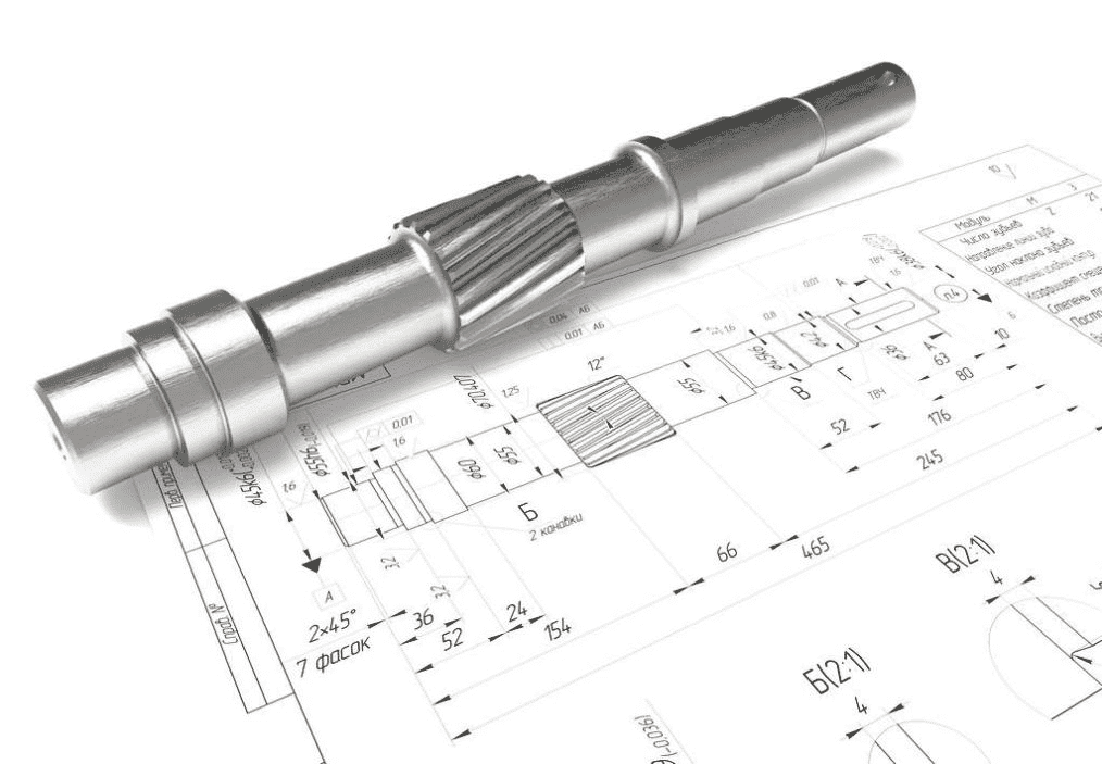
Mechanical part drawings are the most common type of engineering drawing. They provide a detailed representation of a mechanical part, including its dimensions, shape, and composition.
Mechanical part drawings are crucial for manufacturing, as they guide the production process.
A mechanical part drawing typically includes the following sections: title block, drawing number and revision, scale and units of measurement, views and projections, dimensions and tolerances, and geometric symbols and feature control frames.
Technical Drawings for Mechanical Parts
Technical drawings for mechanical parts are more detailed than mechanical part drawings.
They provide information about the materials, manufacturing processes, and quality control standards for a product.
Mechanical parts require precise technical drawings to guarantee that they meet performance specifications and industry standards.
These drawings include features such as surface finishes, tolerances, and performance requirements that are essential for a successful product.
Common Components of Engineering Drawings
Views and Projections
1. Orthographic Projection:
Orthographic projection is a method of representing a three-dimensional object in two dimensions. It provides a detailed view of the object from different angles.
2. Isometric Projection:
Isometric projection is a type of orthographic projection that represents a three-dimensional object at a 45-degree angle.
It provides a more realistic view of the object and is commonly used in architectural and engineering drawings.
Dimensions and Tolerances
Dimensions provide information about the size and shape of a product. They are typically placed on the drawing using dimension lines, extension lines, and arrowheads.
Tolerance symbols and indications provide information about the acceptable variations in size and shape for a product.
They ensure that the product functions correctly and meets the required standards.
Geometric Symbols and Feature Control Frames
Symbolic Representations of Geometric Characteristics
Geometric symbols provide information about the shape and orientation of a product. They include symbols such as circles, squares, and triangles.
Feature control frames for data and control of features
Feature control frames for data and control of features are necessary for precise manufacturing and assembly.
In short, clear and accurate engineering drawings are vital for the successful production of any product.
Detailed Components Of Mechanical Parts Drawing
Mechanical parts drawings are crucial to the successful production of any product. When creating a mechanical parts drawing, it’s important to include several key components.
Here are the components of a mechanical parts drawing:
1. Part identification and numbering:
Part identification and numbering allow for easy identification of each individual component within the larger product.
This helps ensure that all necessary parts are included in the final assembly.
When it comes to part identification and numbering, each component is given a unique identifier to prevent confusion during manufacturing or assembly to ensure that all parties involved understand exactly what is required for production.
2. Geometric dimensioning and tolerancing:
Geometric dimensioning and tolerancing (GD&T) provides specific measurements and tolerances for each feature on the part.
This ensures that every feature is produced accurately, leading to more precise manufacturing and assembly.
3. A bill of materials (BOM) and material specifications:
A bill of materials (BOM) and material specifications outline the exact materials needed for each component.
This ensures consistency throughout the production process, as well as making sure that the correct materials are used.
BOMs provide a list of all necessary materials needed for production. Material specifications outline the specific properties required for those materials.
Both BOMs and material specifications ensure that the correct materials are selected for optimal performance.
4. Sectional views and cutting planes:
Now, let’s dive into sectional views and cutting planes. Sectional views show internal details of a part that would not be visible from an exterior view.
Cutting planes indicate where the section should be taken from in order to reveal these internal details.
These views are crucial for understanding the full picture of a part’s design and functionality.
Importance of Clear and Accurate Engineering Drawings
However, the real importance of clear and accurate engineering drawings lies in their ability to ensure precise manufacturing and assembly.
Without precise drawings, it’s impossible to create a product that meets the exact specifications required. This can lead to costly errors and rework in production.
Furthermore, clear and accurate engineering drawings facilitate communication between designers and manufacturers.
By clearly marking key features and tolerances, designers can ensure that manufacturers understand exactly what is required.
This helps to minimize confusion and mistakes in the production process.
Finally, it’s worth noting that clear and accurate engineering drawings can help minimize errors and rework in production.
By providing precise specifications for each component of a product, manufacturers can ensure that they are producing parts that meet the exact requirements.
This can not only help to reduce waste but it can also improve the overall efficiency in the production process.
Precision Partnership: Engineering Drawing and CNC Collaboration Unveiled
The best way to ensure that engineering drawings are precise and accurate is by partnering with CNC machines.
CNC machines enable manufacturers to create parts quickly and accurately, ensuring that every component is perfect for its intended purpose.
This helps to reduce errors and rework in production while also minimizing time wasted on manufacturing and assembly.
Furthermore, CNC machines allow for complex parts to be created using various materials, eliminating the need for manual labor.
[embedyt] https://www.youtube.com/watch?v=FNYEXjRmDtI[/embedyt]
Engineering Drawing Fundamentals:
Engineering drawings are the fundamental building blocks of the manufacturing industry, providing essential information for manufacturers to produce parts that meet precise specifications.
The basic purpose of engineering drawings is to clearly communicate all the specs required for each component of a product.
This includes essential elements such as dimensions, tolerances, and material specifications.
CNC Technology Overview
CNC (Computer Numeric Control) is a computer-controlled machining process that enables manufacturers to create parts with high precision and accuracy.
CNC machines are programmed to perform specific operations on raw materials, such as drilling, cutting, and shaping.
They can produce components in various shapes and sizes and with varying levels of complexity.
CNC machines are cost-effective and provide greater accuracy than manual labor, making them a popular choice in the manufacturing industry.
Collaborative Workflow between Engineering Drawing and CNC
The collaborative workflow between engineering drawing and CNC involves designers and engineers translating concepts to drawings, and CNC operators interpreting drawings for machining.
The feedback loop and iterative improvements are critical components of this collaborative workflow.
By working together, designers, engineers, and CNC operators can fine-tune the manufacturing process to improve overall efficiency.
Engineering drawings are the backbone of the design process, providing a detailed plan for each component of a product.
These drawings include lines, sections, and dimensions that specify the exact shape and size of each object.
For mechanical parts, accurate technical drawings are especially crucial, as they help to ensure that each part fits together seamlessly and functions properly.
This is particularly important for engine components, where even the smallest error in measurement or placement can lead to disastrous consequences.
To ensure the accuracy of these drawings, designers and engineers must collaborate closely with CNC operators.
A CNC operator is responsible for interpreting the drawings and creating manufacturing plans that will guide the production process.
By working together, designers and CNC operators can ensure that the manufacturing process is as efficient and precise as possible.
1. Designers and Engineers: Translating Concepts to Drawings
The first step in the collaborative workflow between engineering drawing and CNC is for designers and engineers to translate their concepts into technical drawings.
This requires a deep understanding of mechanical engineering principles, as well as the ability to visualize the final product.
The designer must be able to translate their ideas into a format that can be easily understood by others.
2. CNC Operators: Interpreting Drawings for Machining
Once the technical drawings are complete, the CNC operator takes over. Their job is to interpret the drawings and create manufacturing plans that will guide the production process.
Deep knowledge of the machining process is required to ensure that each part fits together properly and meets the design specifications.
They must also be able to use their own judgment when assessing the quality of the final product.
3. Feedback Loop and Iterative Improvements
Throughout the collaborative workflow between engineering drawing and CNC, there is a constant feedback loop between designers, engineers, and CNC operators.
This feedback loop allows for iterative improvements to be made to the design and manufacturing process.
Engineering Drawing Overview: Key Components and Significance in Design
The process of engineering drawing is essential for capturing the intricate details of a design, and it plays a crucial role in mechanical design.
Its key components include the basic drawing, dimensioning, and annotations.
It’s important to note that engineering drawings are not just used for visualizing a design – they are also a valuable source of information for the entire engineering process.
Properly structured drawings help to ensure that products are reliable and manufactured in the most efficient manner possible.
In summary, engineering drawing is an integral part of any successful mechanical design project.
It provides a comprehensive overview of a design, and its accurate technical drawings are essential for the production of high-quality parts.
By collaborating with CNC operators to interpret these drawings, engineers can ensure that products are manufactured accurately and efficiently.
In the end, it all comes down to having the right tools and knowledge to create precision parts that meet customer specifications.
Services We Offer: