What is A Micrometer?
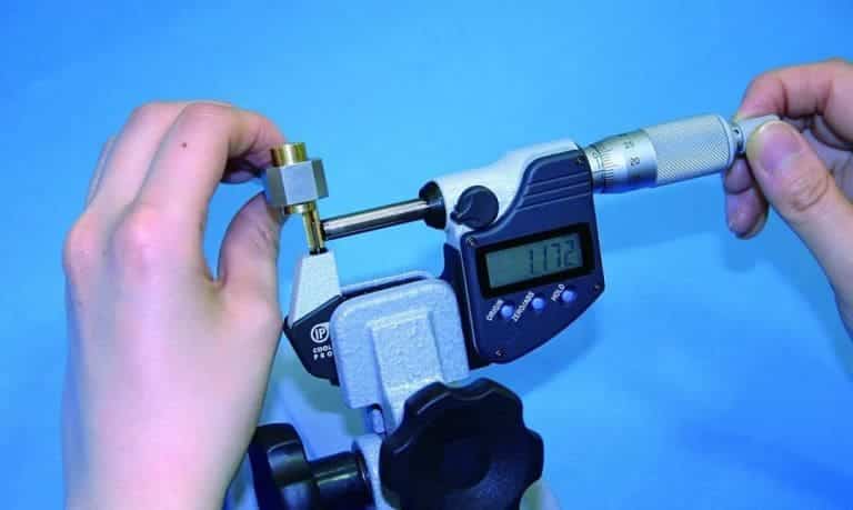
A micrometer (also known as a spiral micrometer) has a higher measurement accuracy than a vernier caliper (the micrometer is accurate to 0.01mm) and is more acute. It is widely used in the measurement of workpieces with high machining accuracy requirements.
The micrometer is used to measure or inspect the outer diameter, inner diameter, depth, thickness, pitch diameter of the thread, and the common normal length of the gear. The use of micrometers can be divided into outer diameter micrometers, inner diameter micrometers, depth micrometers, and thread micrometers.
Micrometer Structure and Reading Principle
Micrometer Structure
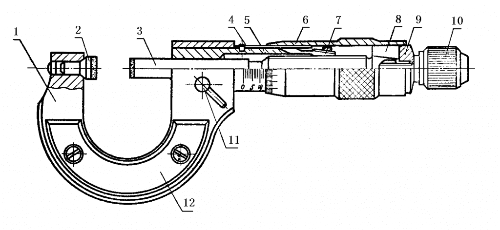
- Scale holder;
- The fixed gauge button;
- Micrometric spiral;
- Threaded sleeve;
- Fixed scale sleeve;
- Micro drum;
- Adjusting screw nut;
- Connector;
- Washer;
- Load device;
- Lock screw;
- Thermal shield.
Micrometer Reading Principle and Method
The outer diameter micrometer is the same as other micrometers. The pitch of the micrometer screw thread is 0.5mm, which is matched with the inner thread on the bushing. When the movable sleeve rotates once, it moves 0.5mm along the axis together with the micrometer screw. The outer conical surface of the left end of the movable casing is divided into 50 grids, so when the movable casing rotates in 1 small grid, the micrometer screw moves along the axis by 0.5mm/50=0.01mm, which is the reading value of the dry scale.
When measuring a workpiece with an outer diameter micrometer, its reading method can be divided into three steps:
- When reading the left side of the edge of the movable casing, the score value shown on the fixed casing must be careful not to miss the score value of 0.5mm that should be read.
- Read the value of the scale line where the movable sleeve is aligned with the reference line on the fixed sleeve.
- Add the above two readings.

Micrometer Measuring Range and Accuracy
The movement of the micrometer screw is 25mm, so the measurement range of the micrometer is generally 25mm. In order to enable the micrometer to measure a wider range of length dimensions to meet the needs of industrial production, the micrometer scale holder is made in various sizes to form micrometers with different measurement ranges.
At present, the size of the measuring range of micrometers produced in China is divided into 0 ~ 25; 25 ~ 50; 50 ~75; 75~100; 100 ~ 125; 125~ 150; 150~175; 175 ~ 200; 200 ~225; 225 ~250; 250~ 275; 275 ~ 300; 300 ~ 325; 325 ~350; 350~375; 375~ 400; 400 ~425; 425~450; 450~475; 475 ~ 500; 500~ 600; 600~700; 700 ~ 800; 800 ~900; 900 ~1000.
The micrometer is divided into grade 0, grade 1, and grade 2 according to manufacturing accuracy. Grade 0 has higher accuracy, grade 1 has higher accuracy, and grade 2 has average accuracy.
How to Use A Micrometer
①Before use, the two measuring anvil surfaces of the micrometer should be wiped clean, and the force measuring device should be rotated to make the two measuring anvil surfaces contact (if the upper limit of measurement is greater than 25mm, a calibration measuring rod or corresponding size should be placed between the two measuring anvil surfaces. The gauge block), there should be no gap and light leakage on the contact surface, and the differential cylinder and the fixed sleeve should be briefly aligned with the zero position.

②When the force-measuring device is rotated, the differential cylinder should be able to move freely and flexibly along the fixed sleeve without any jamming and inflexibility. If the rotation is not flexible, it should be sent to the metering station for maintenance in time.
③Before measurement, the measured surface of the parts should be wiped clean, so as not to affect the measurement accuracy when there is dirt. Micrometers should never be used to measure surfaces with abrasives to avoid damaging the accuracy of the surface.
It is also wrong to use micrometers to measure parts with rough surfaces, which is easy to cause premature wear of the anvil surface.

④When measuring parts with a micrometer, we should hold the rotating cap of the force measuring device to rotate the micrometer screw, so that the surface of the anvil maintains the standard measurement pressure, that is, you can hear the sound of the micrometer, indicating that the pressure is appropriate, and you can start reading. Measurement errors due to measuring pressure differences should be avoided.
It is absolutely not allowed to rotate the differential cylinder to increase the measuring pressure, so that the micro screw is too tight on the surface of the parts, resulting in the deformation of the precision thread due to excessive force, and damage to the accuracy of the micrometer.
Sometimes after the micrometer cylinder is rotated forcibly, although the connection between the micrometer cylinder and the micrometer screw is not firm, the damage to the precision thread is not serious, but after the micrometer cylinder slips, the zero position of the micrometer moves, which will cause a quality accident.
⑤When using a micrometer to measure parts, make sure that the micrometer screw is in the same direction as the dimension of the part being measured.
For example, when measuring the outer diameter, the micrometer screw should be perpendicular to the axis of the part, and should not be skewed. During measurement, while rotating the force measuring device, gently shake the ruler frame, so that the anvil surface and the surface of the part are in good contact.

⑥When measuring parts with a micrometer, it is best to take a reading on the part, and take out the micrometer after loosening, which can reduce the wear of the anvil surface. If it is necessary to take off the reading, apply the brake to lock the micrometer screw, and then gently slide the part out. It is wrong to use the micrometer as a caliper because this will not only cause the measuring surface to wear prematurely but also cause the micrometer to wear out. The screw or ruler frame is deformed and loses accuracy.
⑦When reading the measurement value on the micrometer, be very careful not to misread 0.5mm.
⑧To obtain correct measurement results, measure again at the same location. Especially when measuring cylindrical parts, it should be measured several times in different directions on the same circumference to check whether there is a roundness error on the outer circle of the part, and then measure several times at various parts of the entire length to check whether there is a cylindricity error on the outer circumference of the part, etc.
⑨For workpieces with ultra-normal temperature, do not measure to avoid reading errors.

⑩When using the outer micrometer with one hand, as shown in Figure a, use the thumb and index finger or middle finger to pinch the rotatable sleeve, the little finger hooks the ruler frame and presses it on the palm, and the thumb and index finger rotate the force measuring device. measurable.
When measuring with both hands, can be carried out according to the method shown in Figure (b). It is worth mentioning that there are several wrong ways to use the outer micrometer, such as measuring the workpiece in rotating motion with the micrometer, it is easy to wear the micrometer, and the measurement is inaccurate; Such as the desire to get a faster reading, holding the differential cylinder to swing, which, like collision, will also destroy the internal structure of the micrometer.

(a) One-handed use (b)Two-handed use
Proper Usage

Mistake Usage
The Role of Different Types of Micrometers
- Vernier reading outside micrometer for general outside diameter measurement.
- Small head outer micrometer suitable for measuring precision parts of watches and clocks.
- The pointed outer micrometer is characterized in its structure by a pointed head with a 45° cone shape on the two measuring surfaces. It is suitable for measuring small grooves, such as drill, vertical milling cutter, even grooves tap diameter, and clock gear root circle diameter.
- The wall thickness micrometer is characterized by a spherical measuring surface and a side measuring surface and a special-shaped ruler frame, which is suitable for an outer diameter micrometer for measuring the wall thickness of pipes.
- Plate thickness micrometer, plate thickness micrometer refers to a ruler frame with a spherical side measuring surface and two sides and a special shape, which is suitable for measuring the thickness of the plate.
- Thin-film micrometer for groove diameter measurement, which can reduce measurement error by 5% each time.
- V felt micrometer, odd tap, reamer outside diameter dimension measurement.
- Spline micrometer for gear groove diameter measurement.
- Caliper-type inner micrometer for small diameter, narrow groove width measurement.

 info@yijinsolution.com
 (+86) 188-2253-7569
